Automax logix 3200iq digital positioner – Flowserve Logix 3200IQ Digital Positioner User Manual
Page 3
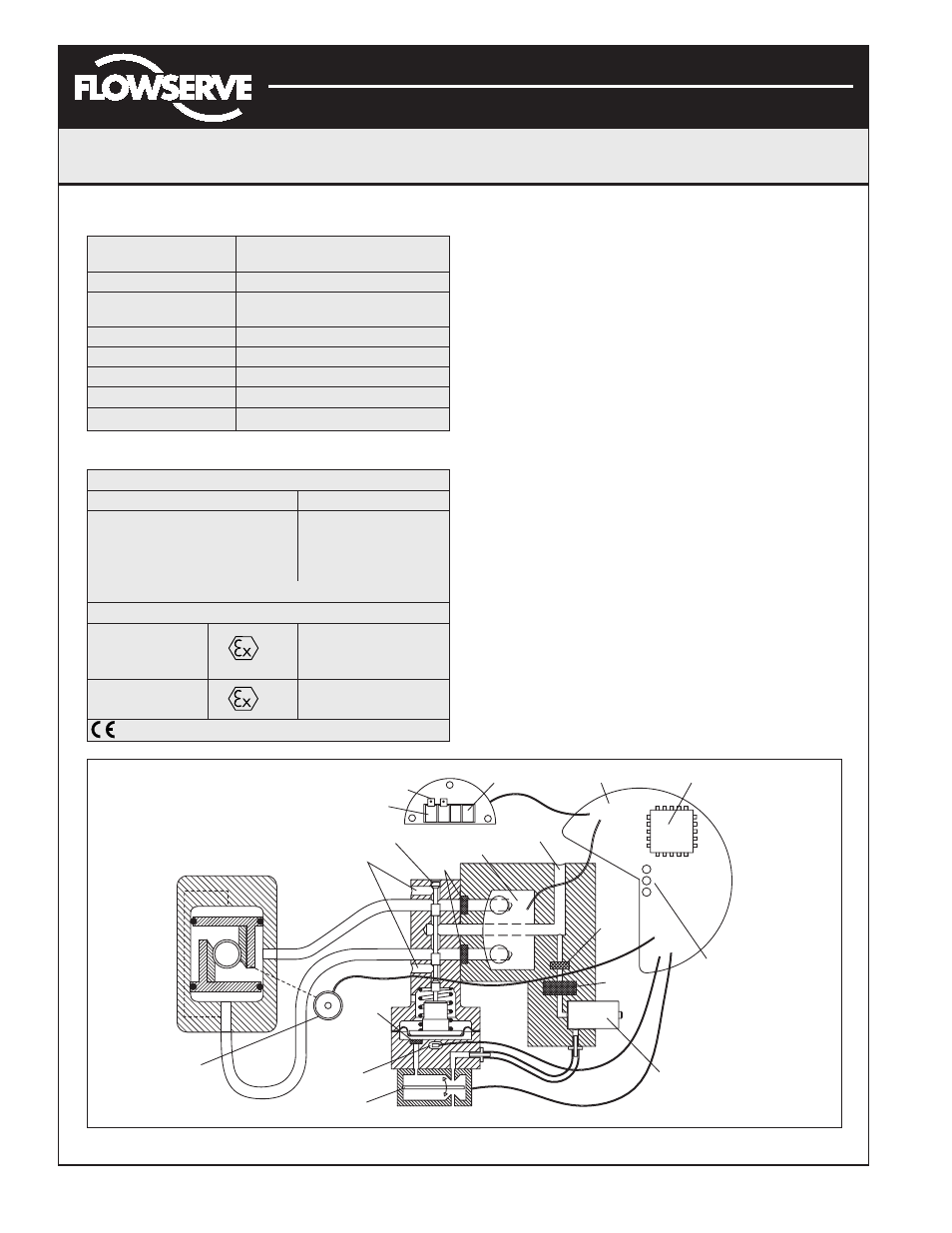
Piezo Valve
Output 2
Output 1
Hall Effect
Sensor
Flame
Arrestor
Exhaust
Spool Valve
Flame
Arrestor
Pressure
Sensor Board
Air Supply
Analog Output Signal
Main PCB
Regulator
Filter
Flame
Arrestor
Digital Position Algorithm
LED
Display
HART
Terminals
Command
Input Signal
Air-to-Open
Configuration
Steam
Position
Sensor
Flowserve Corporation
1350 N. Mountain Springs Parkway
1978 Foreman Dr.
Flow Control Division
Springville, Utah 84663-3004
Cookville, TN 38501
www.flowserve.com
Phone: 801 489 2233
Phone: 931 432 4021
FCD AXAIM3200-00 9/04
Page: 3 of 32
© 2004, Flowserve Corporation, Printed in USA
Automax Logix 3200IQ Digital Positioner
Installation, Operation and Maintenance Instructions
Positioner Operation
The Logix 3200IQ positioner is an electric feedback
instrument. Figure 2 shows a Logix 3200IQ positioner
installed on a double-acting actuator.
The Logix 3200IQ receives power from the two-wire,
4-20 mA input signal. However, since this positioner
utilizes HART communications, two sources can be used
for the command signal: Analog and Digital. In Analog
source, the 4-20 mA signal is used for the command
source. In Digital source, the level of the input 4-20 mA
signal is ignored and a digital signal, sent via HART,
is used as the command source. The command source
selection can be accessed with SoftTools software, the
HART 275/375 communicator, or other host software.
The input signal in percent passes through a
characterization/limits modifier block. The positioner
no longer uses CAMs or other mechanical means to
characterize the output of the positioner. This function
is done in software, which allows for in-the-field
customer adjustment. The positioner has three basic
modes: Linear, Equal Percent (=%) and Custom
characterization. In Linear mode, the input signal is
passed straight through to the control algorithm in a
1:1 transfer. In Equal Percent (=%) mode, the input signal
is mapped to a standard 30:1 rangeability =% curve.
If Custom characterization is enabled, the input signal
is mapped to either a default =% output curve or a
custom, user-defined 21-point output curve. The custom
Figure 2: Logix 3200IQ Digital Positioner Schematic (air-to-open configuration)
Table VI: 4 to 20 mA Analog Output Specifications
Potential Range
40° to 95°
of Rotation
Power Supply Range
12.5 to 40 VDC, (24 VDC typical)
Maximum Load
(Supply voltage - 12.5) / 0.02
Resistance (ohms)
Current Signal Output
4-20 mA
Linearity
1.0% F.S.
Repeatability
0.25% F.S.
Hysteresis
1.0% F.S.
Operating Temperature -40° to 176°F, -40° to 80°C
Table VII: Hazardous Area Certifications
FM/CSA
Intrinsically Safe
Explosion Proof
Class I, Div 1, Groups A, B, C, D
Class I, Div 1,
Groups A, B, C, D
Class II, Div 1, Groups E, F, G
Class II, Div 1,
Groups E, F, G
(See Figure 2 for installation requirements.)
CENELEC
II 1G EEx ia IIC T4, T5
Intrinsically Safe
T4 Ta = -40°C to 80°C
T5 Ta = -40°C to 35°C
Flameproof
II 2 GD EEx d IIB + H
2
T5, Ta = -40°C to 80°C
Compliant