Main pcb assembly – Flowserve 1000 Series Digitial Positioner User Manual
Page 9
FCD AXAIM0064-00 (AUTO-64) 08/04
Page: 9 of 16
© 2004, Flowserve Corporation, Printed in U.S.A.
Logix Series 1000 Digital Positioner
Installation, Operation and Maintenance Instructions
Flowserve Corporation
1350 N. Mountain Springs Parkway
1978 Foreman Dr.
Flow Control Division
Springville, Utah 84663-3004
Cookville, TN 38501
www.flowserve.com
Phone: 801 489 2233
Phone: 931 432 4021
© TriCom, Inc., 2004, All Rights Reserved.
4. Remove the four No. 6-32 screws from the filter
housing and remove filter housing.
5. Remove the old coalescing filter from bore in
interface plate.
6. Insert new coalescing filter into bore on interface plate.
7. Verify that the O-ring is in place in filter housing.
8. Set filter housing over coalescing filter and secure with
four No. 6-32 screws.
9. Replace collector board and reconnect wiring.
Main PCB Assembly
The main PCB assembly contains the circuit board and
processor that perform the control functions of the
positioner. The board is encapsulated in the tray with a
protective silicon coating. This module can be easily
replaced if positioner upgrades are desired. None of the
components inside the tray are serviceable. This module
is to be replaced as a unit.
1. Make sure valve is bypassed or in a safe condition.
2. Disconnect the power and air supply to the unit.
3. Remove the main cover and disconnect the ribbon
cable from the collector board.
CAUTION: To avoid damaging any components,
exercise caution by gently raising the locking tab
to release the ribbon cable.
4. Remove the PCB assembly by removing the three
No. 6-32 screws and lifting tray out of housing.
5. Place the new PCB assembly on bosses inside the
positioner housing.
6. Insert three No. 6-32 screws through the tray into the
threaded bosses and tighten evenly, using a Phillips
screwdriver. Do not overtighten.
7. Reconnect the ribbon cable to the collector board.
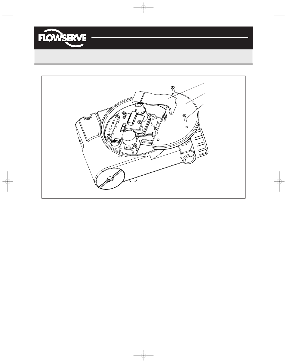
Figure 14: Main PCB Assembly
Ribbon Cable
Main PCB Assembly
Screws (3)
(AXAIM0096-00) Logix 1000 IOM 8/6/04 3:34 PM Page 9