Driver module assembly – Flowserve 1000 Series Digitial Positioner User Manual
Page 6
Logix Series 1000 Digital Positioner
Installation, Operation and Maintenance Instructions
Flowserve Corporation
1350 N. Mountain Springs Parkway
1978 Foreman Dr.
Flow Control Division
Springville, Utah 84663-3004
Cookville, TN 38501
www.flowserve.com
Phone: 801 489 2233
Phone: 931 432 4021
© TriCom, Inc., 2004, All Rights Reserved.
FCD AXAIM0064-00 (AUTO-64) 08/04
Page: 6 of 16
© 2004, Flowserve Corporation, Printed in U.S.A.
Driver Module Assembly
The driver module assembly moves the spool valve by means
of differential pressures on its diaphragm. Air is routed to the
module from the interface plate through a hose that connects
to the assembly through a hose barb with an integral orifice.
Wires from the module connect the hall effect sensor and the
pressure modulator coil to the collector board.
Driver Module Assembly Replacement
To replace the driver module assembly, refer to Figures 9-11,
13, 19 and proceed as outlined below. The following tools
are required:
0.25-inch open-end wrench
0.50-inch hex wrench
Phillips screwdriver.
1. Make sure valve is bypassed or in a safe condition.
2. Disconnect the power and air supply to the unit.
3. Remove the driver module cover, using a 0.50-inch hex
wrench (Figure 11). Do not force the cover. If undue
resistance is encountered, use slots to loosen cover.
4. Remove the spool valve cover by removing the screw
and sliding the cover assembly backwards until the
tab is clear of the slot. Removing the sheet metal cap
from this assembly is not necessary (Figure 13).
5. Being careful not to lose the nylon washers, remove
the two Phillips-head screws that attach the driver
module to the main housing (Figure 10).
6. Remove the spool valve block by removing the two
Phillips-head screws and carefully sliding the block
off the spool (Figure 10).
CAUTION: The spool (extending from the driver
assembly) is easily damaged. Use extreme caution
when handling driver assembly.
7. Remove the tubing from the orifice in the driver
module assembly to the collector board. Using a
0.25-inch open-end wrench, remove the orifice from
the driver module (Figure 11).
8. Remove the two wiring connections that link the driver
module assembly to the collector board (Figure 11).
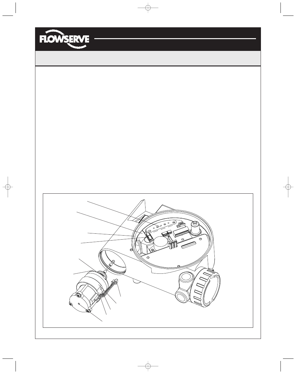
Figure 9: Driver Module Assembly
Collector Board
Pressure
Modulator
Connection
Flat in Housing
Hall Sensor
Connection
Protective
Boot
O-ring
Orient wires forward
Driver Module Assembly
Install orifice after driver module is in housing
Orient this flat parallel to flat in housing
Minimum Pressure Set Screw (factory calibrated)
(AXAIM0096-00) Logix 1000 IOM 8/6/04 3:34 PM Page 6