Spool valve cover – Flowserve 1000 Series Digitial Positioner User Manual
Page 7
FCD AXAIM0064-00 (AUTO-64) 08/04
Page: 7 of 16
© 2004, Flowserve Corporation, Printed in U.S.A.
Logix Series 1000 Digital Positioner
Installation, Operation and Maintenance Instructions
Flowserve Corporation
1350 N. Mountain Springs Parkway
1978 Foreman Dr.
Flow Control Division
Springville, Utah 84663-3004
Cookville, TN 38501
www.flowserve.com
Phone: 801 489 2233
Phone: 931 432 4021
© TriCom, Inc., 2004, All Rights Reserved.
9. Feed the wires back through the housing so they
extend backwards out toward the driver module
opening. This will allow the driver module to thread
out without tangling the wires.
10. Grasp the driver module cap to rotate the entire driver
module. Turn it counter clockwise to remove. After it
is threaded out, carefully retract the driver module
from the housing to avoid the spool.
11. Take the new driver module, and verify that the O-ring
and boot are in place. Lay the wires back and along
the modulator as shown in Figure 9, and hold in place
by hand.
12. Gently direct the driver module onto the housing
bore, making sure the spool does not hit the housing.
Turn the driver module clockwise to thread it into
the housing. Continue rotating module until it
bottoms out.
13. Once the threads are fully engaged, rotate the driver
module counter clockwise until the flat on the driver
module and the flat on the housing are aligned.
This will align the screw holes for the next step.
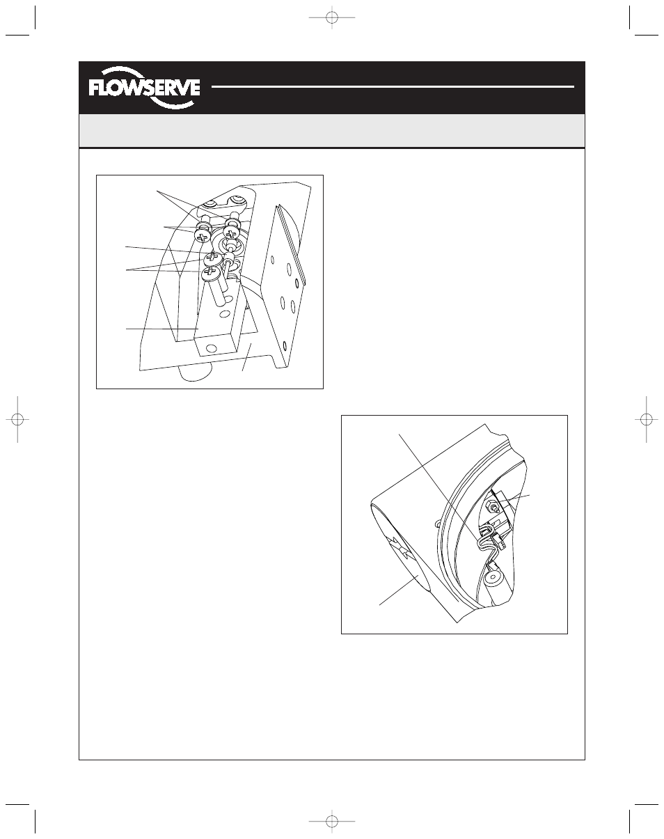
14. Verify that nylon gaskets are in the counter bores in
the driver module retaining screw holes as shown in
Figure 10.
15. Insert two driver-to-housing screws into the driver
housing through the counter-bored holes in the
positioner main housing. Tighten evenly with a
Phillips screwdriver.
16. Feed the driver module wires into the main chamber
of the housing, and connect them to the collector
board.
17. Verify that the three O-rings are in the counter-bores
on the machined platform where the spool valve block
is to be placed (Figure 10).
18. Carefully slide the block over the spool, using the
machined surface of the housing base as a register
(Figure 10). Slide the block toward the driver module
until the two retaining holes line up with the threaded
holes in the base.
19. Install two spool-valve screws and tighten securely
with a Phillips screwdriver.
20. Insert the orifice into the threaded hole in the driver
module assembly. Tighten with a 0.25-inch open-end
wrench (Figure 11). Attach the flexible tubing from the
interface plate to this fitting.
21. Thread driver module cover into driver module bore
in the main housing.
Spool Valve Cover
The spool valve cover incorporates a coalescing filter element
in a two-piece cover. This protects the spool valve chamber
from moisture and provides a low back pressure vent for
exhaust air from the spool valve.
Figure 10: Spool and Block
Figure 11: Driver Module Orifice
Nylon Gaskets
Driver to
Housing Screws
Spool
Spool
Valve
Screws
Spool
Valve
Block
Housing
Driver module wiring
connectors
Driver
Module
Cover
Orifice
(AXAIM0096-00) Logix 1000 IOM 8/6/04 3:34 PM Page 7