Regulator, Internal coalescing filter – Flowserve 1000 Series Digitial Positioner User Manual
Page 8
FCD AXAIM0064-00 (AUTO-64) 08/04
Page: 8 of 16
© 2004, Flowserve Corporation, Printed in U.S.A.
Logix Series 1000 Digital Positioner
Installation, Operation and Maintenance Instructions
Flowserve Corporation
1350 N. Mountain Springs Parkway
1978 Foreman Dr.
Flow Control Division
Springville, Utah 84663-3004
Cookville, TN 38501
www.flowserve.com
Phone: 801 489 2233
Phone: 931 432 4021
© TriCom, Inc., 2004, All Rights Reserved.
Replacing Filter in Spool Valve Cover
1. Make sure the valve is bypassed or in a safe condition.
2. Disconnect the power and air supply to the unit.
3. Remove the spool cover by removing the screw and
sliding the cover assembly backwards until the tab is
clear of the slot. The sheet metal cover may be
removed and cleaned with a brush or by blowing out
with compressed air (Figure 13).
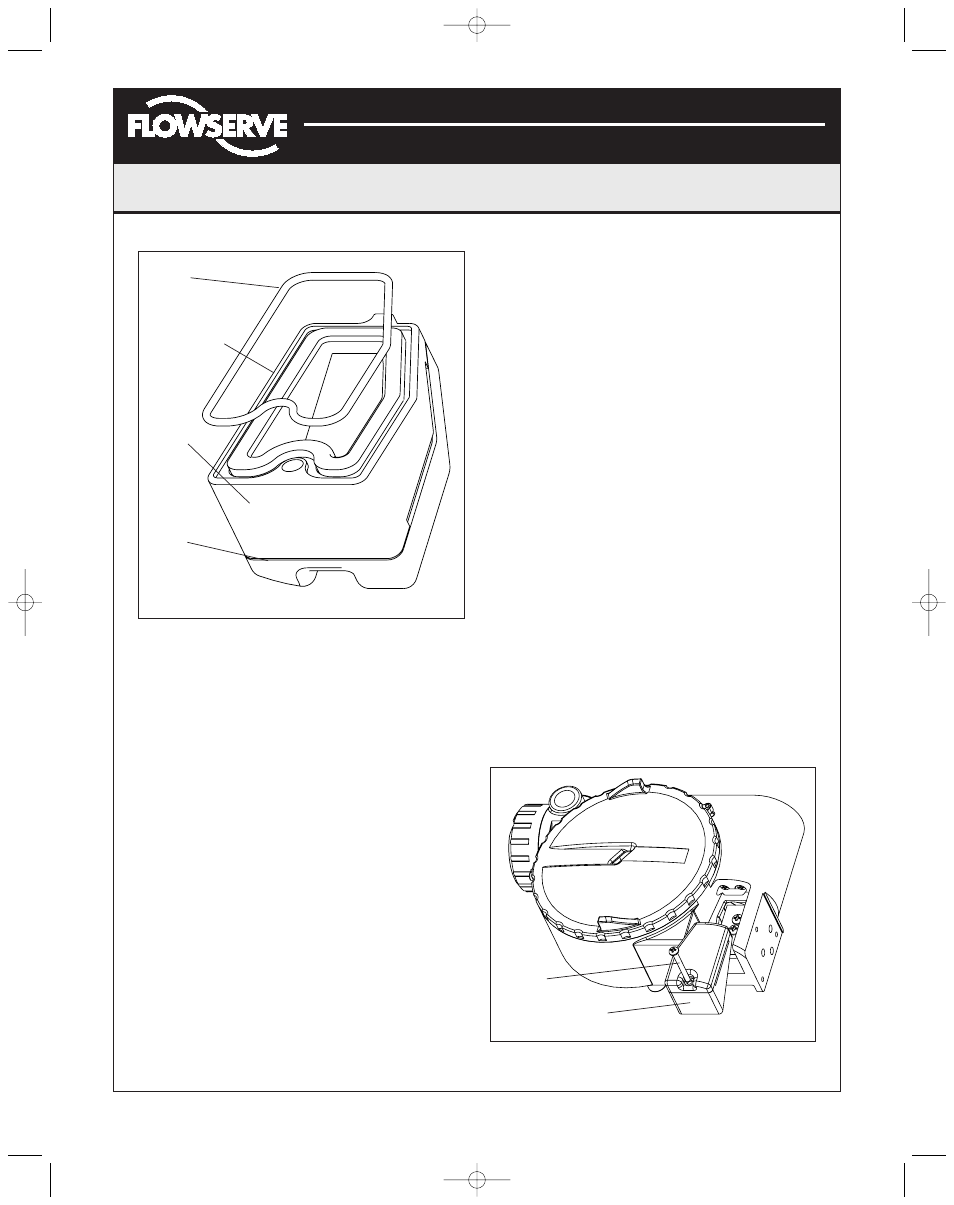
4. Remove the O-ring from around hydrophobic filter
element and set aside (Figure 12).
5. Remove the molded filter element by pulling straight
out of chamber cover vent piece.
6. Place new molded filter element into the chamber cover
vent piece. This element provides part of the track to
secure the O-ring in the next step.
7. Install O-ring into base of chamber cover vent piece as
shown in Figure 12.
8. Place spool valve shroud onto spool valve cover.
9. Place the spool valve cover assembly in place by
setting it on the ramp and sliding it until the tab seats
in the slot, as shown in Figure 13, and secure with
No. 8-32 screw.
Regulator
The regulator reduces the pressure of the incoming
supply air to a level that the driver module can use.
Replacing Regulator
1. Make sure valve is bypassed or in a safe condition.
2. Disconnect the power and air supply to the unit.
3. Remove the main cover and unscrew the regulator
from the interface plate, exercising caution not to
damage the collector board (Figure 19).
4. Verify that the O-rings are in place on the base of the
new regulator.
5. Replace the regulator by threading into the port on the
interface plate.
Internal Coalescing Filter
The internal coalescing filter ensures that supply air is
clean and dry before it gets to the regulator. Because the
air has already been filtered before this point, the element
should not require extended maintenance.
Replacing Input Filter Element (Figure 19)
1. Make sure valve is bypassed or in a safe condition.
2. Disconnect the power and air supply to the unit.
3. Remove the main cover and remove collector board by
disconnecting the wiring and removing three screws
that attach it to the housing. Each cable has its own
unique connector to prevent mistakes in reconnecting.
Figure 12: Spool Valve Cover Assembly
Figure 13: Spool Valve Cover Assembly
O-ring
Hydrophobic
Filter
Spool
Valve
Cover
Spool
Valve
Shroud
Screw
Spool Valve Cover
(AXAIM0096-00) Logix 1000 IOM 8/6/04 3:34 PM Page 8