Cable requirements, Tricom, inc., 2004, all rights reserved – Flowserve 1000 Series Digitial Positioner User Manual
Page 5
Logix Series 1000 Digital Positioner
Installation, Operation and Maintenance Instructions
Flowserve Corporation
1350 N. Mountain Springs Parkway
1978 Foreman Dr.
Flow Control Division
Springville, Utah 84663-3004
Cookville, TN 38501
www.flowserve.com
Phone: 801 489 2233
Phone: 931 432 4021
© TriCom, Inc., 2004, All Rights Reserved.
FCD AXAIM0064-00 (AUTO-64) 08/04
Page: 5 of 16
© 2004, Flowserve Corporation, Printed in U.S.A.
Cable Requirements
The Logix 1200 positioner utilizes the HART Communication
protocol. This communication signal is superimposed on the
DC 4-20 mA current signal. The two frequencies used by the
HART protocol are 1200 Hz and 2200 Hz. In order to prevent
distortion of the HART communication, cable capacitance
and cable length restrictions must be calculated. The cable
length must be limited if the capacitance is too high.
Selecting a cable with lower capacitance/foot rating will allow
longer cable runs. In addition to the cable capacitance, the
network resistance also affects the allowable cable length.
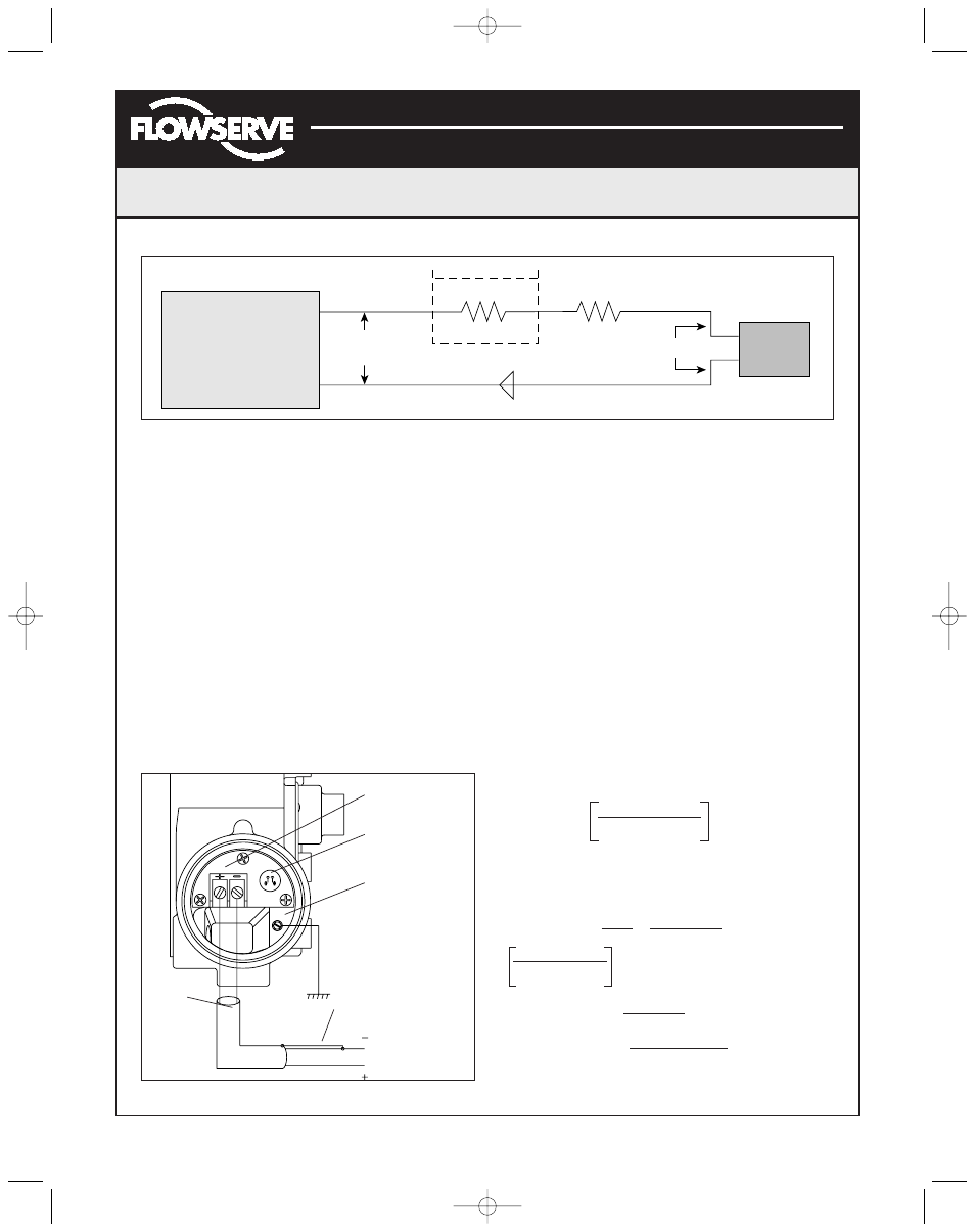
In order to determine if the loop will support the Logix 1200
positioner, perform the following calculation.
Voltage =
The calculated voltage must be greater than 12 VDC in
order to support the Logix 1200 positioner.
Example:
DCS Compliance Voltage = 19 VDC
R
barrier
= 300
Ω
R
wire
= 25
Ω
CURRENT
MAX
= 20 mA
Voltage = 19 VDC - 0.020 A*(300
Ω
+ 25
Ω
)
= 12.5 VDC
The voltage 12.5 VDC is greater than the required
12 VDC; therefore, this system will support the Logix
1200 positioner. The Logix 1200 positioner has an input
resistance equivalent to 600
Ω
at a 20 mA input current.
In order to calculate the maximum network capacitance,
use the formula shown in the next column. (NOTE: To
control cable resistance, No. 24 AWG cable should be used
for runs less than 5000 feet. For cable runs longer than
5000 feet, No. 20 AWG cable should be used.)
65
(R
barrier
+ R
wire
+ 390)
Example: R
barrier
= 300
Ω
R
wire
= 50
Ω
C
cable
= =
Max. Cable Length =
Max. Cable Length = = 3636 ft.
C
network
(uF)
≤
- 0.0032
22 pF 0.000022 uF
foot foot
Compliance Voltage (@Current
MAX
)
- Current
MAX
*(R
barrier
+R
wire
)
Current
Source
Logix
1200
If Present
R
Barrier
Current
Compliance
Voltage
R
Wire
12 VDC
+
-
Figure 7: Compliance Voltage
Figure 8: Field Termination
Field Terminations
HART Connection
Terminals
Housing EARTH
Terminal
Shielded
Cable
Connect Shield at Source
Ground
4-20 mA Current Source
65
(300 + 50 + 390)
0.08 uF
0.000022 uF/foot
C
network
(uF)
C
cable
- 0.0032 = 0.08 uF= C
network
(uF)(Max.)
(AXAIM0096-00) Logix 1000 IOM 8/6/04 3:34 PM Page 5