Basic settings, Switching controller level electrode, Fig. 14 – Flowserve NRG16-41 User Manual
Page 21: Attention, Factory set default node ids
Basic Settings
continued
H
1
1
2
2
3
3
1 2 3
5 6 7
4
8 910
ON
1
2
3
4
5
LW HW
Fig. 14
Attention
■
Do
not assign the same node ID twice within the CAN bus network.
Assigning / changing node ID
If several systems of the same kind are to communicate in one CAN bus network, be sure to assign
one node ID for each individual system component (e. g. controller).
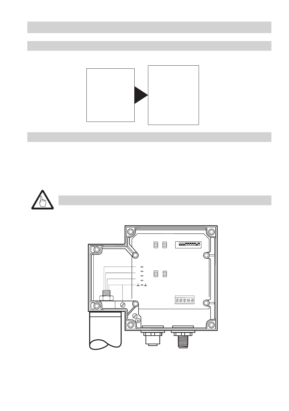
. Undo and remove screws
H. Remove housing cover J.
. Set code switch
M to the required position. Please observe the setting tables on page .
3. Mount housing cover
J and tighten screws H.
M
Factory set default node IDs
NRS 1-40 ID: 001
NRS 1-40.1 ID: 001
NRS 1-41 ID: 006
NRS 1-42 ID: 020
NRS 2-40 ID: 039
NRR 2-40 ID: 040
LRR 1-40 ID: 050
NRG 16-40 ID: 002
NRG 16-40 ID: 003
NRG 16-41.1 ID: 004
TRV 5-40
ID: 005
NRG 16-41 ID: 007
NRG 16-42 ID: 021
NRG 26-40 ID: 041
LRG 16-40 ID: 051
Switching Controller
Level Electrode