Nrg 1, Wiring, Fig. 13 – Flowserve NRG16-41 User Manual
Page 18: Wiring diagram, Screen, Voltage supply 4v dc, Can data line c, Terminating resistor 0 ω
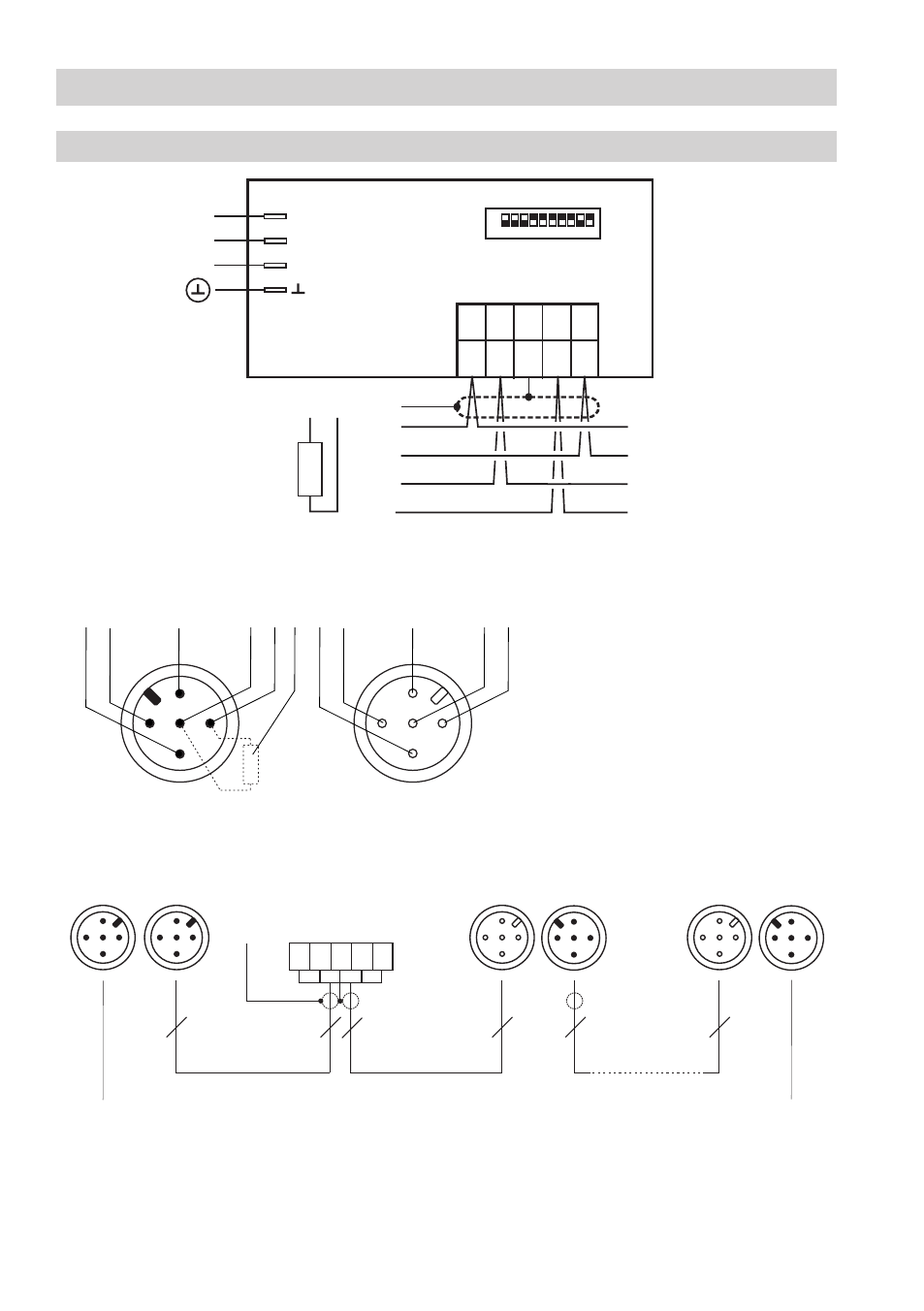
8
1
NRG 1...-41
HW
_
1
2
3
4
5
C
L
S
C
H
+
C
L
H
C
2
3
24V DC
CAN - Bus
S
1 2 3
5 6 7
4
8 910
ON
Wiring
continued
Wiring diagram
e. g. UNITRONIC
®
BUS CAN x x...
e. g. UNITRONIC
®
BUS CAN x x...
Electrode rod
Electrode rod
Electrode rod
Code switch
UNITRONIC
®
is a registered trademark of LAPP Kabelwerke GmbH, Stuttgart
Fig. 13
Terminating resistor 0 Ω, twisted pair cable.
3
5
5
5
5
5
5
+
-
L
C
H
C
S
Coupler with terminating
resistor 0
Ω
Operating
device URB
CEP
Central
earthing
point
Connector with terminating
resistor 0
Ω
Controller
NRS ...
LRR ...
TRS ...
Level electrode
Conductivity electrode
NRG ...
LRG ...
Temperature transmitter
TRV ...
2
1
5 46 3 4
1
52
1
Screen
2
Voltage supply 4V DC+
3
Voltage supply 4V DC-
4
CAN Data line C
H
5
CAN Data line C
L
6
Terminating resistor 0
Ω
This manual is related to the following products: