Wiring – Flowserve NRG16-41 User Manual
Page 17
7
. Undo screws
H and remove housing cover J. Fig. 8
. Slacken plug
O with 7 mm open-end spanner but do not remove. Fig. 9
The electrode terminal box can now be turned through +/– 180°.
3. Turn electrode terminal box into desired position (+/– 80°).
4. Tighten plug
O
with
25 Nm.
5. Set node ID (see sections
“Basic Settings” and “Factory set default node IDs”).
6. Re-attach housing cover
J and fix it by using screws H.
Wiring
NRG 16-41, NRG 17-41, NRG 19-41
Note that screened multi-core twisted-pair control cable is required for the BUS line, e. g. UNITRONIC
®
BUS CAN x x ... mm
or RE-YCYV-fl x x ... mm
.
Prefabricated control cables (with connector and coupler) of various lengths for connecting the
equipment are available as accessories.
The baud rate (data transfer rate) dictates the cable length between the bus nodes and the total power
consumption of the sensor dictates the conductor size.
The baud rate is set via a code switch. Reduce baud if cable is longer than specified in the table. Make
sure that all bus nodes have the same settings.
To protect the switching contacts fuse circuit with .5 A (anti-surge fuse) or according to TRD
regulations (.0 A for 7 hrs operation).
If a max. cable length of more than 125 m (up to 1000 m) is desired, make sure to modify the
baud rate settings accordingly. Please refer to pages 21 and 22.
UNITRONIC
®
is a registered trademark of LAPP Kabelwerke GmbH, Stuttgart
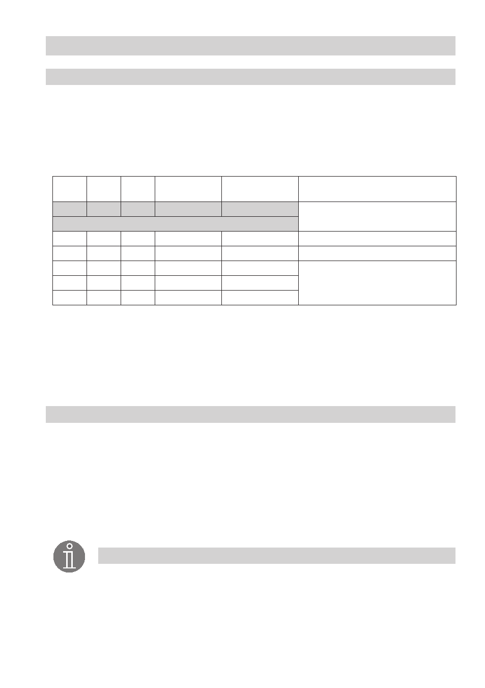
S 8
S 9
S 10
Baud rate
Cable length
Number of pairs
and conductor size [mm
2
]
OFF
ON
OFF
250 kBit/s
125 m
x x 0.34
Factory setting
ON
ON
OFF
5 kBit/s
50 m
x x 0.5
OFF
OFF
ON
00 kBit/s
335 m
x x 0.75
ON
OFF
ON
50 kBit/s
500 m
on request, dependent on
bus configuration
OFF
ON
ON
0 kBit/s
000 m
ON
ON
ON
0 kBit/s
000 m
Aligning terminal box
Note
■
Wire the control cable according to the wiring diagram with connector and coupling.