Installation, Measuring sensor org 12, org 22, Fig.8 – Flowserve OR 52-5 User Manual
Page 16
16
Installation
continued
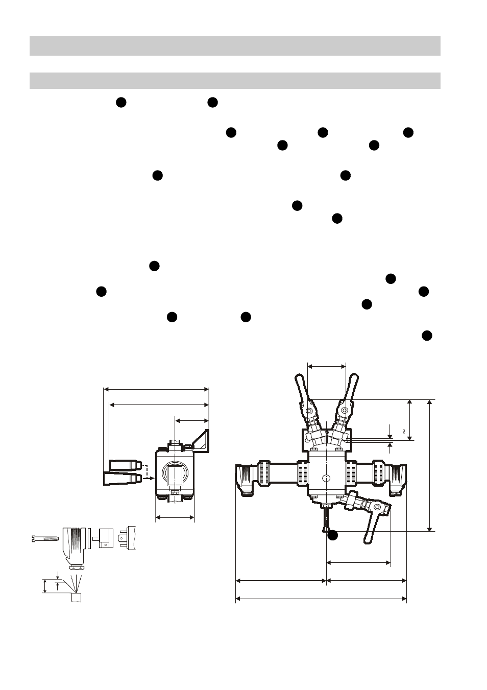
Measuring Sensor ORG 12, ORG 22
continued
The cover flange and lower flange of the measuring sensor can be screwed turned
through 90°.
1. Screw in nipples with threaded ends , screwed unions and ball valves
supplied with the sensor into upper cover flange and lower flange or directly at
the inlet, outlet or purging points. Use teflon tape for sealing.
2. The screwed unions facilitate positioning of the ball valves so that the levers
can be arranged in one plane (front).
3. Fit the ORG 12/ORG 22 with the mounting bracket provided in an accessible
place. If the sensor is used on ships weld mounting bracket to its support.
4. For the inlet and outlet lines of the sensor use 12 mm OD Ermeto, 10 mm OD gas
pipe or suitable flexible tubes (for rinsing purposes).
5. Fit the light receiver in an accessible place. It can then be easily removed so that
visual inspection of the fluid is possible. The interchange of light emitter and light
receiver is possible after loosening the union nuts (inside) from the housing .
When refitting, take care of correct fit of locating pins of the housing in the grooves
provided in light emitter and receiver . Tighten union nuts.
Be sure the equipment is damp proof – condensate on the outside of glass cylinder
results in excessively high readings.
C
J
A
Z
B
C
J
Z
B
Y
Y
D
Q
D
T
T
Q
D
U
78
70
135
140
80
7
90
31
5
135
175
200
375
Fig.8
5
40