Flowserve 510si Series Digital Positioner User Manual
Page 8
8
®
User Instructions Logix 510si - LGENIM0510-0
2 12/13
NOTE: The switch settings in the Configuration box
are activated only by pressing the Quick-Cal button.
Operation of CONFIGURATION DIPswitch Setup -The
first 5 DIP Switches are for basic configuration.
a. Air
Action
- This must be set to match the configuration
of the valve/actuator mechanical tubing connection and
spring location since these determine the air action of
the system.
Ê
UÊ ATO (air-to-open)- Selecting ATO if increasing
output pressure from the positioner is tubed so
it will cause the valve to open.
Ê
UÊ ATC (air-to-close)- Selecting ATC if increasing
output pressure from the positioner is tubed so
it will cause the valve to close.
b.
Signal at Closed - Normally this will be set to 4 mA for
an Air-to-open actuator, and 20 mA for an Air-to-close
actuator configuration.
Ê
UÊ -iiVÌ}Ê{ÊÊÜÊ>iÊÌ
iÊÛ>ÛiÊvÕÞÊVÃi`ÊÊ
when the signal is 4mA and fully open when the
signal is 20 mA.
Ê
UÊ -iiVÌ}ÊÓäÊÊÜÊ>iÊÌ
iÊÛ>ÛiÊvÕÞÊVÃi`ÊÊ
when the signal is 20 mA and fully open when
the signal is 4 mA.
c. Characteristic
Ê
UÊ -iiVÌÊi>ÀÊvÊÌ
iÊ>VÌÕ>ÌÀÊ«ÃÌÊÃ
Õ`ÊLiÊÊ
directly proportional to the input signal.
Ê
UÊ /
iÊr¯Ê«ÌÊÜÊV
>À>VÌiÀâiÊÌ
iÊ>VÌÕ>ÌÀÊÊ
response to the input signal based on a stan-
dard 30:1 equal percent rangeability curve.
d. Tight
Shutoff
Ê
UÊ -iiVÌÊ"ÊÌÊ
>ÛiÊÌ
iÊ«ÃÌiÀÊvÕÞÊÃ>ÌÕÀ>ÌiÊÊ
the actuator closed at a signal less than 1%.
Ê
UÊ -iÌÌ}ÊÌ
iÊÃÜÌV
ÊÊÌ
iÊ"vvÊ«ÃÌÊ`Ã>LiÃÊÊ
this
feature.
e. Auto
Tune -This switch controls whether the positioner
will auto tune itself every time the quick cal button is
pressed
UÊ
On enables an automatic tuning feature that will auto-
matically determine the positioner gain settings every
time a “Quick-Cal” is performed. The gain settings can
be modified after a calibration by adjusting the rotary
“Gain” switch.
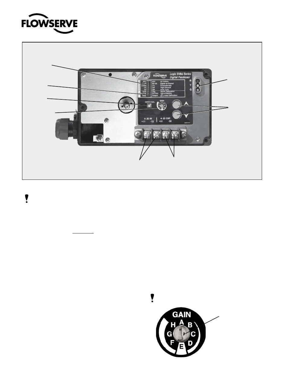
NOTE: there is a small black arrow indicating the selec-
tion. The slot does not indicate the chosen gain.
Figure 4: Logix 510si Local Interface
Configuration
Switches
Gain selector
4-20 mA Input
4-20 mA Feedback
(Optional)
Jog Calibrate
Buttons
LED Status
Lights
Quick-Cal
Switch
Calibration
Switches
Indicator arrow