Flowserve CPXS User Manual
Page 31
CPXS, CPXNS and CPXPS USER INSTRUCTIONS ENGLISH 71569250 07-11
Page 31 of 48
flowserve.com
r) Tighten the locknut and torque up to the values
given in section 6.6.
6.11.4 Containment shell assembly - single
containment metallic shell
a) Install the containment shell gasket [4590.2 ]in
the groove in the casing cover [1220].
b) Install the metallic shell [224.2].
c) Install the backing ring [1240].
d) Install and tighten the 6 mm capscrews
[6570.1] to 11 Nm (8 lbf•ft). Torque screws
crosswise.
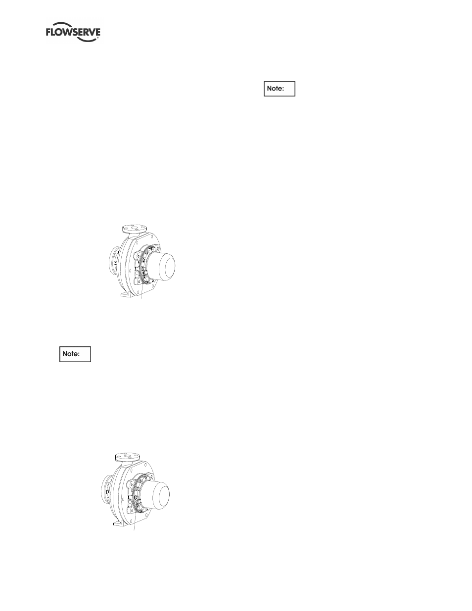
6.11.5 Containment shell assembly - single
containment PEEK shell
a) Install the containment shell gasket [4590.2] in
the groove in the casing cover [1220].
b) Install shell [224.1] with slotted temperature tap
as shown.
Slotted tap for
temperature monitoring
c) Install and tighten the 6 mm capscrews and
washers [6570.1] to 11 Nm (8 lbf•ft). Torque
screws crosswise
It is important that washers are not
omitted otherwise excessive damage to PEEK
shell flange will occur.
6.11.6 Containment shell assembly - dual
containment
a) Install the containment shell gasket [4590.2] in
the groove in the casing cover [1220].
b) Install the metallic shell [241.2].
c) Install dual containment O-ring [4610].
d) Install PEEK shell [241.1] with pressure tap as
shown.
Threaded tap for dual containment
pressure monitoring
e) Install and tighten the 6 mm capscrews and
washers [6570.1] to 11Nm (8 lbf•ft). Torque up
screws crosswise.
It is important that washers are not
omitted otherwise excessive damage to PEEK
shell flange will occur.
6.11.7 Final bearing housing assembly
a) Install the 2 jack bolts, (previously used for
disassembly), into the bearing housing [3200]
and thread in until they extend as follows:
•
Model 80
26 mm (1.0 in.)
•
Model 100
45 mm (1.75 in.)
•
Model 150
95 mm (3.75 in.)
b) It is recommended that a liquid sealant,
Hylomar Universal Blue or equivalent, is
applied between the bearing housing and
casing cover. [4590.3] on sectional
arrangement refers.
c) Position the outer assembly [230] over the shell
until the jacking screws rest against the casing
cover [1220].
d) Back out the jack screws ALTERNATELY,
ensuring spigot between casing cover and
bearing housing is fully located and square.
e) Remove the jacking bolts.
f) Install the four bearing housing to cover bolts
[6570.3] and torque crosswise to 54 Nm (40
lbf•ft).
g) Tighten the foot bolt(s) [6570.5].
h) Re-check the frame shaft [2100.2] for freedom
of rotation.
i)
Install the coupling.
j)
Align the coupling. (See section 4.5, Initial
alignment.)
k) Ensure that all other items have been re-
attached and all fasteners tightened, then
follow the instructions in the Installation
sections.