Flowserve CPXS User Manual
Page 14
CPXS, CPXNS and CPXPS USER INSTRUCTIONS ENGLISH 71569250 07-11
Page 14 of 48
flowserve.com
4.5.2
Alignment methods
Pump and driver must be isolated
electrically and the half couplings disconnected.
The alignment MUST be checked.
Although the pump will have been aligned at the
factory it is most likely that this alignment will have
been disturbed during transportation or handling. If
necessary, align the motor to the pump, not the pump
to the motor.
Alignment is achieved by adding or removing shims
under the motor feet and also moving the motor
horizontally as required.
In some cases where the alignment cannot be
achieved it will be necessary to move the pump
before recommencing the above procedure.
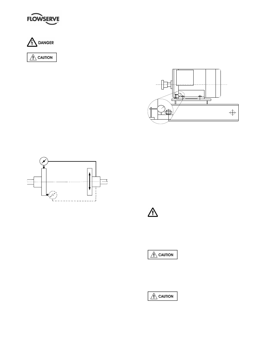
For couplings with narrow flanges use a dial
indicator as shown. The alignment values are
maximums for continuous service.
Parallel
Angular
Permissible misalignment limits at working
temperature:
•
Parallel alignment
- 0.25 mm (0.010 in.) TIR maximum
•
Angular alignment
- 0.3 mm (0.012 in.) TIR maximum for
couplings not exceeding 100 mm (4 in.) flange
diameter
- 0.5 mm (0.020 in.) TIR maximum for
couplings over 100 mm (4 in.) diameter
When checking parallel alignment, the total
indicator read-out (TIR) shown is twice the value of
the actual shaft displacement.
When the electric motor has sleeve bearings it is
necessary to ensure that the motor is aligned to run
on its magnetic centreline. Refer to the motor
manual for details. A button (screwed into one of
the shaft ends) is normally fitted between the motor
and pump shaft ends to fix the axial position.
Align in the vertical plane first, then horizontally by
moving motor. Maximum pump reliability is obtained
by near perfect alignment of 0.05 - 0.075 mm (0.002 -
0.003 in.) parallel and 0.05 mm (0.002 in.) per 100 mm
(4 in.) of coupling flange diameter as angular
misalignment.
4.5.3
Check for soft foot
This is a check to ensure that there is no undue
stress on the driver holding down bolts; due to non-
level baseplate or twisting. To check, remove all
shims and clean surfaces and tighten down driver
to the baseplate. Set a dial indicator as shown in
sketch and loosen off the holding down bolt while
noting any deflection reading on the dial test
Indicator - a maximum of 0.05 mm (0.002 in.) is
considered acceptable but any more will have to be
corrected by adding shims. For example, if the dial
test indicator shows the foot lifting 0.15 mm (0.006
in.) then this is the thickness of shim to be placed
under that foot. Tighten down and repeat the same
procedure on all other feet until all are within
tolerance.
Complete piping as below and see sections 4.7,
Final shaft alignment check up to and including
section 5, Commissioning, startup, operation and
shutdown, before connecting driver and checking
actual rotation.
4.6 Piping
Protective covers are fitted to the pipe
connections to prevent foreign bodies entering during
transportation and installation. Ensure that these
covers are removed from the pump before connecting
any pipes.
4.6.1
Suction and discharge pipework
Never use pump as a support for
piping.
Maximum forces and moments allowed on the pump
flanges vary with the pump size and type. To
minimize these forces and moments that may, if