Flowserve MEN User Manual
Page 23
MEN
USER INSTRUCTIONS ENGLISH 71576288 – 11-09
Page 23 of 36
®
→
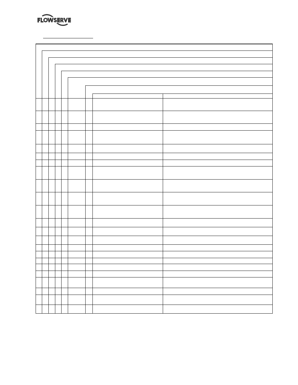
Local signalization table:
Non auto position switch fault
General fault
Failure risk
Not starting
Motor in operation
LED color
Audible alarm
Description
Meaning
Green
Live electronics
Live electronic circuits (at least one of both power sources is
present)
x
Yellow
x
Mains shortage
Pre-heating and charger electric circuits are not powered by
mains anymore (180s delay)
Green
Battery 1 loading or Battery 2 loading
Shows that corresponding battery is loading (1 LED per battery)
x
Yellow
x
Charger 1 fault or Charger 2 fault
Shows that corresponding battery charger does not deliver the
necessary voltage at output during loading period (1 LED per
charger) or that the mains power supply is absent.
x
Yellow
x
Battery 1 fault or Battery 2 fault
Shows that corresponding battery cannot assume its function (1
LED per battery)
x
Red
x
Cabinet-starter connection
Cabinet-starter connection non guaranteed
x
Green
Motor in operation
Shows that the pump is operating
Green
Pressure switch 1 start-up
Shows that the pump has been started by pressure switch 1 or
that the start-up sequence in progress was initiated by pressure
switch 1
Yellow
Pressure switch 2 start-up
Shows that the pump has been started by pressure switch 2 or
that the start-up sequence in progress was initiated by pressure
switch 2
Green
Auto position
Pressure switch 1 or 2 controller is in automatic mode [element
controlled with the corresponding pressure switches 1 or 2, in
automatic mode]
x
Red
Non auto position
Pressure switch 1 or 2 controller is on STOP or MANUAL
position [element controlled with the corresponding pressure
switches 1 or 2 and STOP position or MANUAL mode]
x
Red
x
Not started
Shows that the pump did not start automatically at the end of the
start-up sequence
x
Red
x
Water temperature
Shows that cooling water temperature exceeds its limit (engine
overheating)
x
Red
x
Filter clogging (optional)
Shows a filter clogging [indicates that the heat-exchanger circuit
water filter is clogged]
x
Red
x
Oil pressure
Shows an insufficient oil pressure
x
Red
x
Diesel level
Shows an insufficient diesel level
x
Red
x
Engine reheating
Shows that the preheating system is out of service
x
Red
x
Engine water level
Shows an insufficient tank water level
x
Red
x
Recovery tank water level
Shows an insufficient level in the recovery or secondary tank
x
Red
x
Priming tank level (optional)
Shows an insufficient water level in the priming tank (for sump
suction pumps) and triggers an engine start-up.
x
Red
x
Local sprinkler temperature
Shows that temperature is < 8°C in the local sprinkler water ta nk
x
Red
x
Ventilation sluice blades (optional)
Shows that the ventilation sluice blades in the source room are
not opened when diesel engine is operating
x
Red
x
Pressure switch lines
Shows that a short circuit between the cables of the pressure-
switch
* No red or yellow indicators may be on when the operator leaves the room.