Flowserve MEN User Manual
Page 15
MEN
USER INSTRUCTIONS ENGLISH 71576288 – 11-09
Page 15 of 36
®
Forces and moments values are applied to the
whole flanges and not flange-by-flange. For their
sharing out on the pump flanges, refer to standard
NFCR 13 391.
Ensure piping and fittings are flushed
before use.
Ensure piping for hazardous liquids is
arranged to allow pump flushing before removal of
the pump.
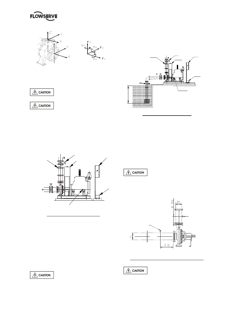
4.5.2 Suction piping
4.5.2.1 Design of a flooded suction line
The suction line must be as short and direct as
possible, never mount an elbow directly on the inlet
flange of the pump.
Non return
valve
Diesel engine
Battery
Switching
enclosure
Tank
Valve
Flooded suction configuration
a) Avoid sharp elbows or sudden narrowing. Use
convergent
≤
20° (total angle).
b) Arrange the piping so that there are no air
pockets (no bulges).
c) If high points cannot be avoided in suction line,
provide them with air relief cocks.
d) In case of frost risks, the piping in question has to
be marked out.
e) If a strainer is necessary, its net area should be
three or four times the area of the suction pipe.
f) If an inlet valve is necessary, choose a model with
direct crossing.
Do not tighten flanges before the final
check (see § 4.5.3).
4.5.2.2 Design of a suction lift line
The inlet pipe must be as short and as direct as
possible, never place an elbow directly on the pump
inlet nozzle.
Non return
valve
Switching
enclosure
Valve
Tank
Battery
Diesel engine
S
u
ff
ic
ie
n
t
im
m
e
rs
io
n
:
I
Sump suction configuration
a) Avoid sharp elbows or sudden narrowing. Use
convergent
≤
20° (total angle) with upright
generating.
b) Arrange that the suction piping is inclined
upwards towards the pump ensuring that there are
no peaks.
c) In case of frost risks, the piping in question has to
be marked out.
d) If a foot valve is necessary, do not oversize it
because it would generate pulsations (valve
beating).
Do not tighten flanges before the final
check (see § 4.5.3).
If necessary, a control manometer can be connected
on the piping.
Installation of control manometers Class I
Do not tighten flanges before the final
check (see § 4.5.3).
I
≥
3 x D
Control manometer (suction)
with glycerin bath
Control manometer
(discharge) with
glycerin bath