Flowserve LR Worthington User Manual
Page 38
LR, LRV, LLR and LR-S USER INSTRUCTIONS ENGLISH 71569088 08-10
Page 38 of 48
flowserve.com
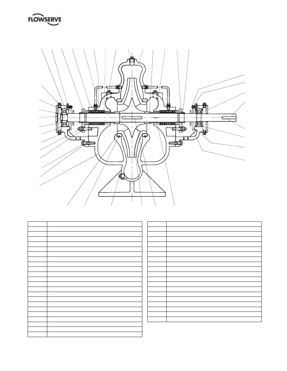
8.2 Sectional drawings – LR double entry impeller, grease lubricated, gland packed
1220
3712
6541
3126
3011.1
6569.4
3645
4120 4134
4130
1630
6569.3
6569.1
1214
2100
6700.2
3011.2
6569.2
3853
4420
1213
6569.5
2200
6572
6580
6570.3
1690
6814.2
4610.1 2450
2910.1
1500
6814.1
6700.1
4590.1
4590.2
2540
3260
6570.4
3200
(Drawing taken from A336/040, sheet 1, rev -)
8.2.1 Parts list – LR double entry impeller
Ref. no.
Description
1213
Casing half - lower
1214
Casing half - upper
1220
Cover
1500
Casing wear ring
1630
Throttling bush
1690
Bush (dowel)
2100
Shaft
2200
Impeller
2450
Shaft sleeve
2540
Flinger (liquid)
2910.1
Shaft nut
3011.1
Ball bearing
3011.2
Ball bearing
3126
Shim **
3200
Bearing housing
3260
Bearing cover
3645
Disc spacer *
3712
Bearing nut
3853
Grease nipple
4120
Gland
4130
Gland packing
4134
Lantern ring
4420
Sealing pipe
4590.1
Gasket
4590.2
Gasket
4610.1
O-ring
6541
Lockwasher
6569.1
Plug
6569.2
Plug
6569.3
Plug
6569.4
Plug
6569.5
Plug
6570.1
Screw
6570.2
Screw
6570.3
Screw
6570.4
Screw
6572
Stud
6580
Nut
6700.1
Key
6700.2
Key
6814.1
Grub screw
6814.2
Grub screw
* Fitted on 2.1/2LR13 pump size only.
** Not required for 10LR17 and 19LR18 pump sizes.