Flowserve LR Worthington User Manual
Page 29
LR, LRV, LLR and LR-S USER INSTRUCTIONS ENGLISH 71569088 08-10
Page 29 of 48
flowserve.com
6.9 Examination of parts
Used parts must be inspected before
assembly to ensure the pump will subsequently run
properly.
In particular, fault diagnosis is essential to enhance
pump and plant reliability.
6.9.1 Casing, seal housing and impeller
a) Inspect for excessive wear, pitting, corrosion,
erosion or damage and any sealing surface
irregularities.
b) Replace as necessary.
6.9.2 Shaft and sleeve (if fitted)
Replace if grooved, pitted or worn.
6.9.3 Gaskets and O-rings
After dismantling, discard and replace.
6.9.4 Bearings
a) It is recommended that bearings are not re-used
after any removal from the shaft.
b) The plain liquid lubricated bearings may be re-used
if both the bearing bush and bottom shaft sleeve
show no sign of wear, grooving or corrosion attack.
(It is recommended that both the bush and sleeve
are replaced at the same time.)
6.9.5 Bearing isolators, labyrinths or shaft seal
rings (if fitted)
a) The lubricant, bearings and shaft seal rings are to
be inspected for contamination and damage. If
oil bath lubrication is utilised, these provide useful
information on operating conditions within the
bearing housing.
b) If bearing damage is not due to normal wear and
the lubricant contains adverse contaminants, the
cause should be corrected before the pump is
returned to service.
c) Labyrinth seals and bearing isolators, if fitted as
options, should be inspected for damage but are
normally non-wearing parts and can be re-used.
d) Shaft seal rings are not totally leak free devices.
Oil from these may cause staining adjacent to the
bearings.
6.10 Assembly
To assemble the pump consult the sectional
drawings, see section 8, Parts list and drawings.
Ensure threads, gasket and O-ring mating faces are
clean. Apply thread sealant to non-face sealing pipe
thread fittings. Coat the outside diameter of the dowel
bushings with pipe compound prior to installation.
6.10.1 LR/LLR
6.10.1.1 Impeller wear rings
a) Impeller rings (when fitted) should be heated up
to approximately 100 ºC (212 ºF) using a hotplate
or hot oil bath and then slipped onto the impeller
and pressed down to the shoulder. (Do NOT use
a steel hammer to knock them into position.)
b) Drill and tap 3 holes approximately 120 degrees
apart into the diametral mating faces of the ring
and impeller and insert socket head grub screws.
(The existing half tapped holes from the removed
impeller ring cannot be re-used.)
6.10.1.2 Pre-assembly of casing gasket
a) Fit casing gasket to the bottom half horizontal
flange using a small amount of contact adhesive to
prevent movement when the top half is fitted. Do
not apply adhesive to the top surface of the gasket.
b) It is important that the external corner of the
casing gasket face and the stuffing box face is as
sharp as possible.
Do not chamfer with a file.
c) If necessary trim gasket to match volute profile.
Do not trim to stuffing box face at this stage.
6.10.1.3 Rotating element and bearing housing
a) Ensure all gaskets and O-rings are renewed and
replaced in the correct position during assembly.
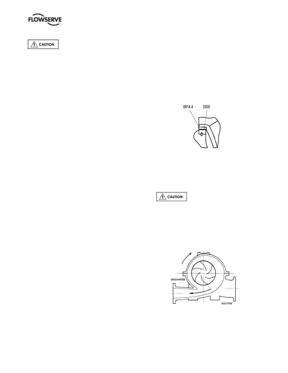
b) Assemble the impeller on the shaft. It is
important to mount the impeller so that the vane
tips point away from the apparent flow direction.
The rotor always rotates towards the expanding
section of the volute
c) If working on a two-stage LLR pump, the
interstage sleeve and interstage bush, complete
with anti-rotation grub screw, must be fitted on to
the shaft between the two impellers.