Flowserve T-series Thrust Bearing Pot User Manual
Page 10
USER INSTRUCTIONS T-SERIES THRUST BEARING POT ENGLISH 26999907 01-2013
Page 10 of 24
flowserve.com
4
INSTALLATION
Equipment operated in hazardous locations
must comply with the relevant explosion protection
regulations. See section 1.6.4, Products used in
potentially explosive atmospheres.
4.1 Thrust bearing pot installation
Pots are either delivered to the customer fully
assembled except for the oil/cooling piping
extension, or pre-installed in the pump.
Before installation remove all items from the pump
discharge head.
a) Remove any debris and thoroughly clean the
surface receiving the pot with solvent. Apply a
thin film of mineral oil to the surface.
b) Remove the screws [6570.2] from the pot, the
adjusting nut [2909] and the oil flinger, oil
thrower [2540].
c) Remove the key [6700.1] from the pump shaft.
Thoroughly clean, with solvent if necessary, the
exposed surface of the shaft and apply a thin
film of mineral oil to it.
d) Install the pot and the rest of the assembly in
the pump. Take care not to damage the pump
shaft during the pot installation and to properly
match the alignment fits of the pump and pot.
e) Rotate the pot assembly on its receiving
surface to match up the holding holes.
f) Install the key [6700.1]. The keyway position is
reached by turning the centering sleeve [2470].
g) Re-install the pot holding bolts.
h) Re-install the oil flinger, oil thrower [2540].
i)
Re-install the adjusting nut [2909].
j)
Regulate the pump rotor axial play by turning,
as necessary, the adjusting nut [2909].
k) Re-install the screws [6570.2].
l)
Re-install the items removed from the
discharge head and the pot piping extensions.
Use Heldite or similar proprietary pipe thread
sealant to seal the piping extensions, where
customer practices permit PTFE based pipe
sealants or PTFE tape these can also be
utilized.
m) Fill the pot with lubricant up to the required
level. Open the vent plug [6521] while filling.
For 7000s and 7000s + 6000s series
the oil level is the centre of the oil level sight
glass; for 29000s + 22000s series the oil level
is indicated in the sectional drawing.
n) Check the oil level before operation. Also,
when specified, check that the piping system is
ready to provide proper cooling to the pot.
4.2 Optional Bearing Gard™
installation
4.2.1
Preparation before installation
a) Remove the oil seal from the housing.
b) Check to ensure the housing bore is free from
contaminants, nicks and burrs or sharp edges.
c) Check the shaft and remove any burrs or sharp
edges on the shaft keyway and trademark
stamps on the shaft.
d) Thoroughly clean the shaft and housing bore.
e) Concentricity of the housing bore to the shaft is
to be maintained within 0.13 mm (0.005 in.)
TIR.
4.2.2
Bearing Gard™ installation
a) Do not disassemble the Bearing Gard™
[4330.2]: it is designed to be installed as a unit.
b) Lubricate the O-rings, the shaft and housing
bore with the lubricant provided.
c) Align the Bearing Gard™ [4330.2] in the
housing so the drain slot is located on the
bottom.
d) Install the Bearing Gard™ [4330.2].
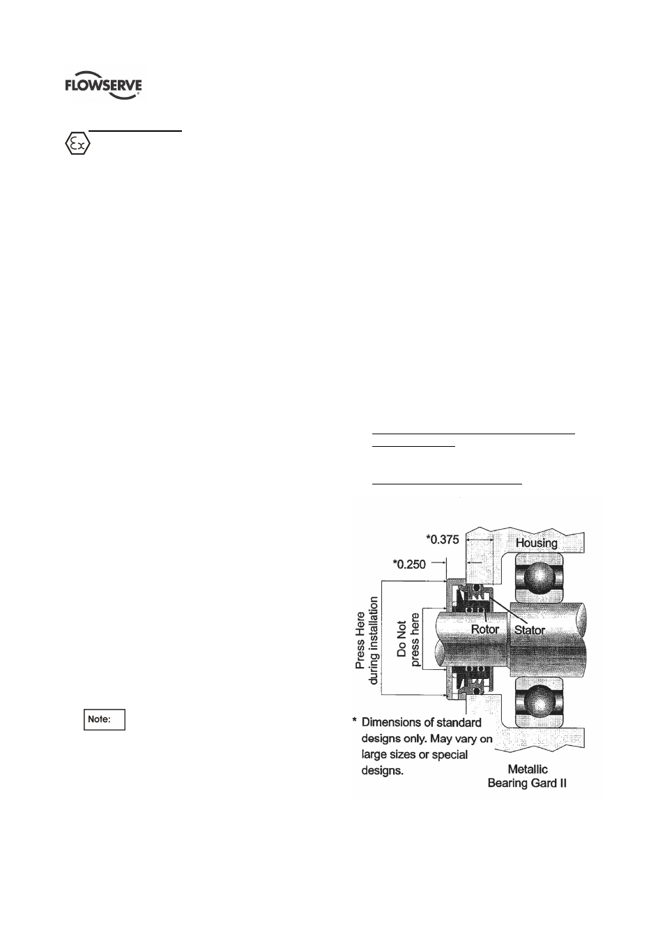
Original-style Bearing Gard™ and Metallic
Bearing Gard™ ll. Use an arbour press to
push on the outer portion of the stator. Do not
use a hammer.
Non-metallic Bearing Gard™ ll. Install using
hand pressure only.
Metallic Bearing Gard™ II