3 description, 1 configurations, 2 name nomenclature – Flowserve WPG IDP User Manual
Page 11: 3 design of major parts, 4 performance and operating limits, Configurations (3.1), Design of major parts (3.3), Name nomenclature (3.2), Performance (3.4)
WPG and WPH USER INSTRUCTIONS ENGLISH 26999969 10-12
Page 11 of 40
flowserve.com
3 DESCRIPTION
3.1 Configurations
This is a robust centrifugal pump design for a wide
range of applications.
3.2 Name nomenclature
The pump size will be engraved on the nameplate
typically as below:
50WPG160
Nominal discharge branch size in mm
W
– Cast iron design
C
– Stainless steel design
PG
– Standard, grease lubricated bearings
PH
– Heavy duty build, oil lubricated bearings
Nominal maximum impeller diameter in mm
The typical nomenclature above is the general guide
to the D-line pump configuration description.
Identify the actual pump size and serial number from
the pump nameplate. Check that this agrees with the
applicable certification provided.
3.3 Design of major parts
3.3.1 Pump casing
The pump casing is designed with a horizontal
centreline end inlet and a vertical centreline top
outlet, which makes it self-venting. For ease of
maintenance, the pump is constructed so that pipe
connections do not have to be disturbed when
internal maintenance is required.
3.3.2 Impeller
A shrouded impeller with hub rings is fitted.
3.3.3 Shaft
The large diameter stiff shaft, mounted on bearings,
has a keyed drive end.
3.3.4 Bearing bearings and lubrication
The pump is fitted with ball and/or roller type bearings
which may be configured differently dependent on use.
The bearings may be oil or grease lubricated.
3.3.5 Seal housing
The seal housing has spigots between the pump
casing and bearing housing for optimum concentricity.
A fully confined gasket forms the seal between the
pump casing and the seal housing. The design
enables one of a number of sealing options to be fitted.
3.3.6 Shaft seal
The mechanical seal(s) attached to the pump shaft
seals the pumped liquid from the environment. Gland
packing may be fitted as an option.
3.3.7 Driver
The pump is driven by a close-coupled electric motor.
The position of the terminal box can be changed by
rotating the complete motor. To do this, remove the
fasteners from the motor flange, rotate the motor and
re-fit the fasteners.
3.3.8 Accessories
Accessories may be fitted when specified by the
customer.
3.4 Performance and operating limits
This product has been selected to meet the
specifications of the purchase order. (See section 1.5.)
These pumps are generally fitted with TEFC motors
with an ambient temperature limit of 40 °C. Specific
pumps may be fitted with motors to suit client's
requirements with other ambient temperature limits -
see motor nameplate for details.
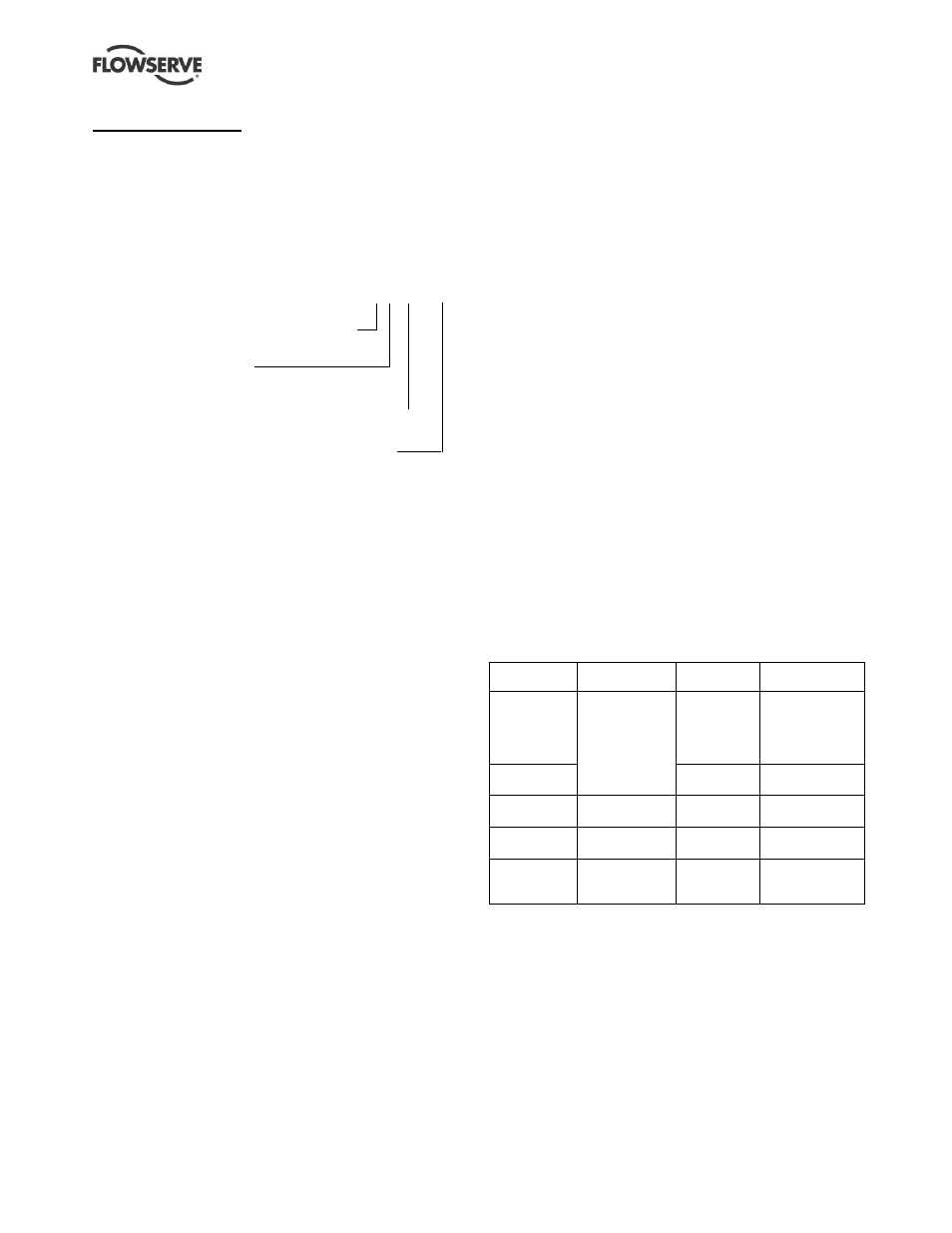
3.4.1 Pressure limits
The operating pressure has been selected to meet
your specified requirements. See paragraph 1.5,
Duty conditions, for details.
Pump
units
Construction
Casing test
pressure
Casing working
pressure
All pump sizes
except
125-225,
200-401
and 150-500
Cast iron,
bronze and
stainless
steel
24 bar
(348 psi)
16 bar
(232 psi)
125-225
15 bar
(217 psi)
10 bar
(145 psi)
200-401
Cast iron and
bronze
24 bar
(348 psi)
16 bar
(232 psi)
200-401
Stainless steel
16 bar
(232 psi)
10.6 bar
(154 psi)
150-500
Cast iron,
bronze and
stainless steel
12 bar
(174 psi)
8 bar
(116 psi)
The pressure and temperature operating limits for the
flanges are in accordance with the relevant National or
International standards unless advised otherwise.
Heating/cooling jackets for seal or stuffing box are
designed for operation up to 5 bar (72.5 psi).
Jacketed pump casings for CPG and CPH units only
are designed for operation up to 5 bar (72.5 psi).