Flowserve MENBLOC 60Hz User Manual
Page 22
MENBLOC 60Hz USER INSTRUCTIONS ENGLISH 71559945 - 02/13
Page 22 of 36
flowserve.com
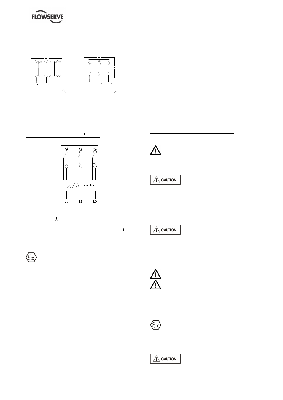
Connection wiring diagram for three phase motors
For Direct on-line starting
Delta connection
Star connection
Wire up the motor terminals according to the
voltage supply, in accordance with the nameplate
fixed on the motor and the connection wiring
diagram displayed inside the terminal box, as
shown above.
When using a separate
∆
/ Stator
Motors of 3.0 kW or larger may be wired up for
star/delta (
∆
/ ) starting on 380/415 V supply. All
connections strips must be removed from the
terminal box and 6 wires connected to the
∆
/
starter, as shown above.
4.5 Protection systems
The following protection systems are
recommended particularly if the pump is installed
in a potentially explosive area or is handling a
hazardous liquid. If in doubt consult Flowserve.
If there is any possibility of the system allowing the
pump to run against a closed valve or below
minimum continuous safe flow a protection device
should be installed to ensure the temperature of
the liquid does not rise to an unsafe level.
If there are any circumstances in which the system
can allow the pump to run dry, or start up empty, a
power monitor should be fitted to stop the pump or
prevent it from being started. This is particularly
relevant if the pump is handling a flammable liquid.
If leakage of product from the pump or its
associated sealing system can cause a hazard it is
recommended that an appropriate leakage
detection system is installed.
To prevent excessive surface temperatures at
bearings it is recommended that temperature or
vibration monitoring are carried out. See sections
5.5.3 and 5.5.4.
If a defect of cooling can lead to temperature
higher than those acceptable a system of cooling
surveillance must be installed.
Except when explicitly required by the customer in
the specifications, when a possibility of reverse
rotation exists the customer must install a reverse
rotation protection device.
The customer must install all equipment required
to avoid water hammer.
5 COMMISSIONING, START-UP,
OPERATION AND SHUTDOWN
These operations must be carried out by
fully qualified personnel.
5.1 Direction of rotation
Starting or operating pumps with
the wrong direction of rotation can be harmful to
the pumps. Ensure that the pump rotation is the
same as the arrow on the pump casing.
It is preferable to check the direction of rotation
before installing the coupling. If not, the pump
must be filled in with the liquid before start-up.
If maintenance work has been
carried out to the site's electricity supply, the
direction of rotation should be re-checked as
above in case the supply phasing has been
altered.
5.2 Guarding
Guarding is supplied fitted to the pump set.
If this has been removed or disturbed ensure
that all the protective guards around the pump
coupling and exposed parts of the shaft are
securely fixed.
5.3 Priming and auxiliary supplies
Where there is any risk of the pump being run
against a closed valve generating high liquid and
casing external surface temperatures it is
recommended that users fit an external surface
temperature protection device.
Ensure all electrical, hydraulic,
pneumatic, sealant and lubrication systems (as
applicable) are connected and operational.