Flowserve MENBLOC 60Hz User Manual
Page 20
MENBLOC 60Hz USER INSTRUCTIONS ENGLISH 71559945 - 02/13
Page 20 of 36
flowserve.com
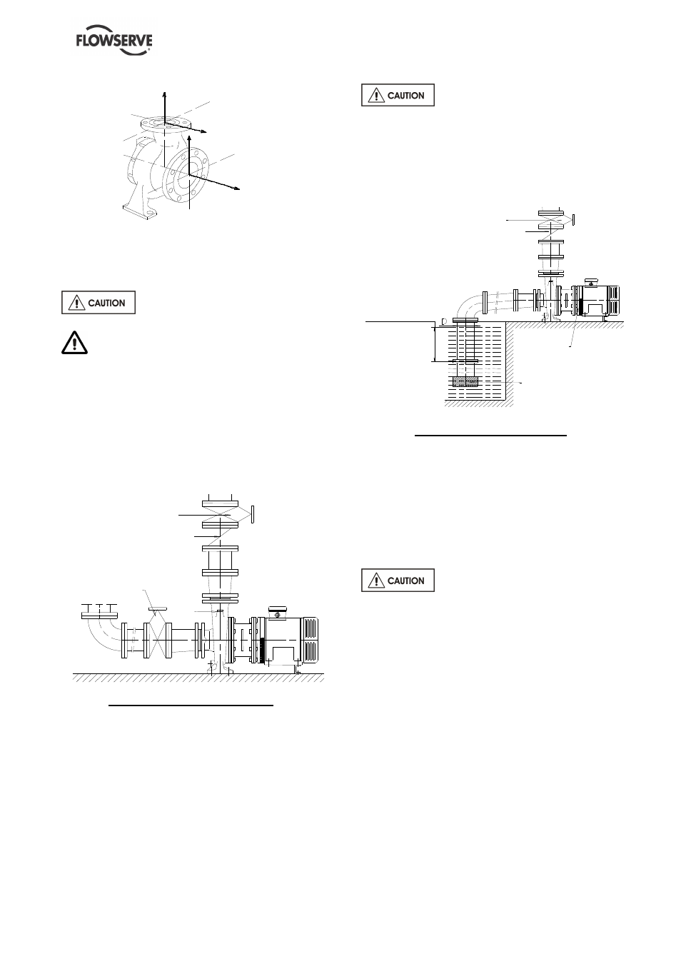
Fv
Fh
Fv
Fh
Forces and moments values are applied to the
whole flanges and not flange-by-flange. For their
sharing out on the pump flanges, refer to standard
NFCR 13 931.
Ensure piping and fittings are
flushed before use.
Ensure piping for hazardous liquids is
arranged to allow pump flushing before removal of
the pump.
4.3.2 Suction piping
4.3.2.1 Design of a flooded suction line
The suction line must be as short and direct as
possible, never mount an elbow directly on the
inlet flange of the pump.
Continuous flow valve
MENBLOC
Non-return valve
Valve
Flooded suction configuration
a) Avoid sharp elbows or sudden changes of
diameter. Use reducers with
≤
20° total angle.
b) Arrange the piping so that there are no air
pockets.
c) If high points cannot be avoided in suction line,
install air relief valves.
d) If a strainer is necessary, its net area should
be three or four times the area of the suction
pipe.
e) If an inlet valve is necessary, choose a model
with straight line flow.
Do not tighten flanges before the
final check (see § 4.3.4).
4.3.2.2 Design of a suction lift line
The inlet pipe must be as short and as direct as
possible, never place an elbow directly on the
pump inlet nozzle.
V alve
N on-return valve
IM M ER S IO N : I
S U FFIC IE N T
M EN BLO C
Inlet-strainer
I
≥
3 x D
Sump suction configuration
a) Avoid sharp elbows or sudden changes of
diameter. Use reducers with
≤
20° total angle.
b) Arrange that the suction piping is inclined
upwards towards the pump ensuring that there
are no peaks.
c) If a foot valve is necessary, do not oversize it
because it would generate pulsations (valve
hammering).
Do not tighten flanges before the
final check (see § 4.3.4).
4.3.3 Discharge piping
4.3.3.1 Design of a discharge line
a) If discharge line is provided with a divergent,
its total angle will be between 7° and 12°.
b) Install the discharge valve after the non-return
valve downstream.
The non-return valve will be set in the discharge
pipe to protect the pump from any excessive
pressure surge and from reverse rotation.
If necessary, a pressure gauge or pressure sensor
for pump or system control can be connected on
the piping