Priming and auxiliary supplies, Starting the pump, Running the pump – Flowserve U-MAG INNOMAG User Manual
Page 20: Stopping and shutdown, 2 priming and auxiliary supplies, 3 starting the pump, 4 running the pump, 5 stopping and shutdown
U-MAG ENGLISH 26999990 10-14
Page 20 of 40
5.2 Priming and auxiliary supplies
5.2.1 Auxiliary supplies
Ensure all electrical, hydraulic,
pneumatic, sealant and lubrication systems (as
applicable) are connected and operational.
5.2.2 Filling and priming
Ensure inlet pipe and pump casing
[1100] is completely full of liquid before starting
continuous duty operation.
Priming may be carried out with an ejector, vacuum
pump, interceptor or other equipment, or by flooding
from the inlet source.
When in service, pumps using inlet pipes with foot
valves may be primed by passing liquid back from the
outlet pipe through the pump.
5.3 Starting the pump
a)
CLOSE the discharge valve.
Fully open the suction valve. Pump requires a
flooded suction.
b)
Do not operate pump with suction valve
closed. Operating pump more than a few minutes
after suction valve closed may cause bearing
failure.
c) Fully open discharge valve to complete priming.
Turn back the discharge valve until it is 1/4 to 1/2
open.
d)
Continuous operation against a closed
discharge valve may cause pump to overheat.
e) Start motor and check the outlet pressure.
f) If the pressure is satisfactory, SLOWLY open the
outlet valve.
g)
Do not run the pump with the outlet
valve closed for a period longer than 10 seconds.
h) If NO pressure, or LOW pressure, STOP the
pump. Refer to section 7, Troubleshooting, for
fault diagnosis.
5.4 Running the pump
Care must be taken when operating pump.
Safety gloves are essential. Loose clothing must not
be worn.
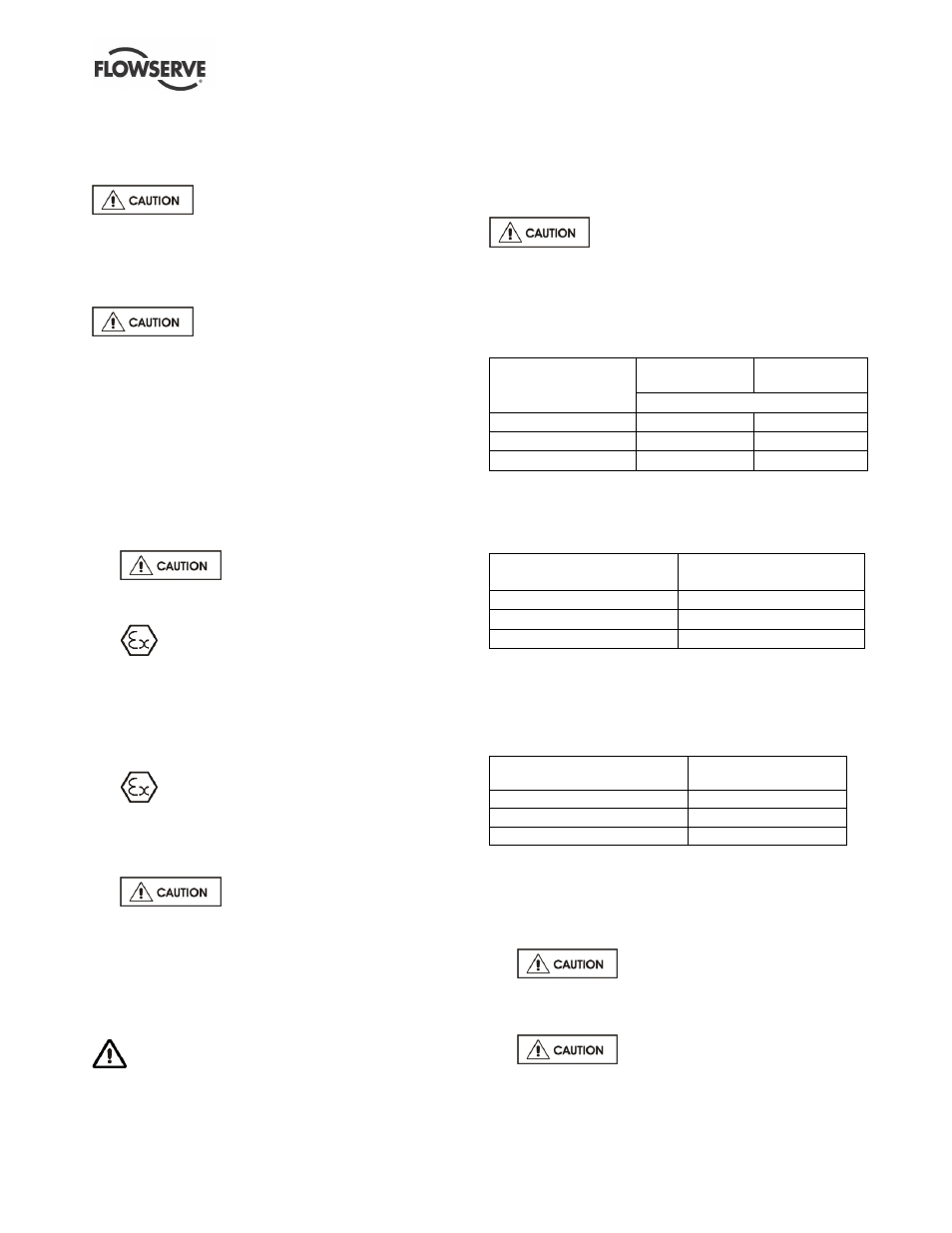
5.4.1 Normal vibration levels, alarm and trip
For guidance, pumps generally fall under a classification
for rigid support machines within the International
rotating machinery standards and the recommended
maximum levels are based on those standards.
Alarm and trip values for installed
pumps should be based on the actual measurements
taken on the pump in the fully commissioned as new
condition. Measuring vibration at regular intervals will
then show any deterioration in pump or system
operating conditions.
Vibration velocity
–
unfiltered
Horizontal pumps
15 kW
Horizontal pumps
> 15 kW
mm/s (in./sec) r.m.s.
Normal N
3.0 (0.12)
4.5 (0.18)
Alarm N x 1.25
3.8 (0.15)
5.6 (0.22)
Shutdown trip N x 2.0
6.0 (0.24)
9.0 (0.35)
Where a unit is utilized in a vertical shaft
configuration with a duck-foot bend onto the pump
suction, the following apply:
Vibration velocity
–
unfiltered
Vertical configurations
mm/s (in./sec) r.m.s.
Normal N
7.1 (0.28)
Alarm N x 1.25
9.0 (0.35)
Shutdown trip N x 2.0
14.2 (0.56)
5.4.2 Stop/start frequency
Pump sets are normally suitable for the number of
equally spaced stop/starts per hour shown in the
table below. Check capability of the driver and
control/starting system before commissioning.
Motor rating kW (hp)
Maximum stop/starts
per hour
Up to 15 (20)
15
Between 15 (20) and 90 (120)
10
Above 90 (120)
6
Where duty and standby pumps are installed it is
recommended that they are run alternately every
week.
5.5 Stopping and shutdown
a)
Close the discharge valve, but
ensure that the pump runs in this condition for no
more than a few seconds.
b) Stop the pump.
c)
For prolonged shut-downs and
especially when ambient temperatures are likely
to drop below freezing point, the pump must be
drained or otherwise protected.