Installation, Location, Part assemblies – Flowserve U-MAG INNOMAG User Manual
Page 14
U-MAG ENGLISH 26999990 10-14
Page 14 of 40
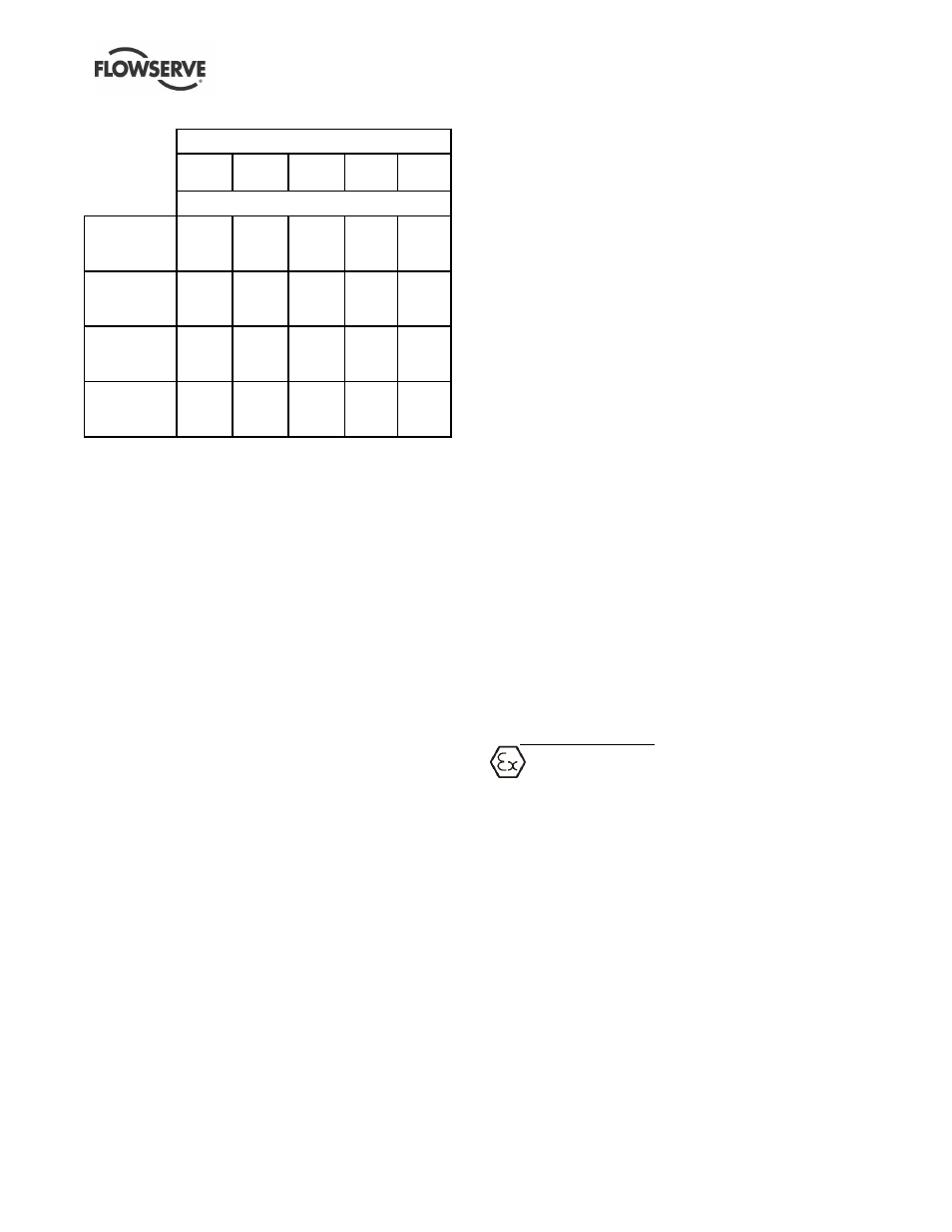
Figure 3-2
Temperature - °C (°F)
-29
(-20)
-18
(0)
38
(100)
93
(200)
121
(250)
Pressure - barg (psig)
ANSI,
ISO, JIS
Slotted
14
(203)
14
(203)
14
(203)
14
(203)
14
(203)
ASME
B16.42
Class 150
17.2
(250)
17.2
(250)
17.2
(250)
16.2
(235)
15.5
(225)
EN 1092-2
(ISO) PN
16
16
(232)
16
(232)
16
(232)
16
(232)
16
(232)
JIS
B2239
10K
14
(203)
14
(203)
14
(203)
14
(203)
14
(203)
3.5.3
Energy Efficiency Operation of Pumps
The pump supplied will have been selected from
Flowser
ve’s extensive product line to have optimum
efficiency for the application. If supplied with an
electric motor then the motor will meet or exceed
current legislation for motor efficiency. However it is
the way the pump is operated which has the greatest
impact on the amount and cost of energy used during
the operating life of the pump. The following are key
points in achieving minimum operating cost for the
equipment:
a) Design the pipe system for minimum friction
losses
b) Ensure that the control system switches off the
pump when not required
c) In a multi-pump system run the minimum number
of pumps
d) Try to avoid systems which by-pass excess flow
e) Avoid as far as possible controlling pump flow by
throttle valves
f) When commissioned, check that the pump
operates at the duty specified to Flowserve
g) If it has been found that the pump head and flow
exceed that required, trim the pump impeller
diameter
h) Ensure that the pump is operating with sufficient
NPSH available.
i)
Use variable speed drives for systems which
require variable flow. A VFD for an induction
motor is a particularly effective way of achieving
speed variation and energy/cost reduction
j)
Notes for VFD usage
a) make sure that the motor is compatible
with VFD
b) Do not over-speed the pump without
checking the power capability with
Flowserve
c) On systems with high static head, speed
reduction is limited. Avoid running the
pump at a speed which gives low or zero
flow
d) Do not run at a low speed and flow rate
which lets solid settle out of suspension
in the pipe work
e) Do not use a VFD for a fixed flow
requirement; it will introduce power
losses
k) Select high efficiency motors
l)
If replacing a standard motor with a high
efficiency motor it will run faster and the pump
could take more power. Reduce the impeller
diameter to achieve energy reduction
m) If the pump system pipe work or equipment is
changed or process duty is changed, check that
the pump is still correctly sized
n)
Periodically check that the pipe system has not
become corroded or blocked
o)
Periodically check that the pump is operating at
the flow, head and power expected and that the
efficiency has not reduced with erosion or
corrosion damage.
4 INSTALLATION
Equipment operated in hazardous locations
must comply with the relevant explosion protection
regulations. See section 1.6.4, Products used in
potentially explosive atmospheres.
4.1 Location
The pump should be located to allow room for access,
ventilation, maintenance and inspection with ample
headroom for lifting and should be as close as
practicable to the supply of liquid to be pumped. Refer
to the general arrangement drawing for the pump set.
4.2 Part Assemblies
The supply of motors and baseplates are optional.
As a result, it is the responsibility of the installer to
ensure that the motor is assembled to the pump and
aligned as detailed in section 4.5 and 4.8.