5 commissioning, start-up, operation and, Shutdown, 1 pre-commissioning procedure – Flowserve CPXV fitted with Mark 3 ASME hydraulics User Manual
Page 17: Pre-commissioning (5.1), 5 commissioning, start-up, operation and shutdown
CPXV with Mark 3 ASME hydraulics ENGLISH 71569291 12-14
Page 17 of 44
flowserve.com
For Category 2 equipment the monitoring must create
an alarm to the plant operator or shut down the pump.
For equipment to category 1/2 or 1/3 with external flush
or filtered product flush, the flow to each line bearing
must be separately monitored and temperature sensors
fitted on each line bearing that is connected to the
pump control system. The monitoring equipment must
be suitable for the hazardous area.
For equipment to category 1/2 or 1/3 the presence of
seal barrier liquid and the temperature of the inboard
seal must both be monitored and connected to the
pump control to create an alarm signal to operators, or
to shut down the pump.
See also sections 5.8.2 to 5.8.6.
The protection sensors will generally be fitted by
Flowserve, but the connection to the pump control
system will often be by the installer of the pump.
Installers must ensure that the instructions of the
sensor manufacturer are followed, that any additional
components are suitable for the zone in which they
are to be installed, and that their trip levels are set
and checked during commissioning. The protective
systems must also be periodically checked in
accordance with the sensor manufacturer’s
instructions or with local site standards.
When clean process liquids are used to flush
bearings the user must periodically check that there
is no contamination entering the sump.
5 COMMISSIONING, START-UP,
OPERATION AND SHUTDOWN
These operations must be carried
out by fully qualified personnel.
Contact the factory for recommendations for
operation with pumpage of any fluid other than what the
pump was specfiically designed for.
5.1 Pre-commissioning procedure
Prior to starting the pump it is essential that the
following checks are made.
Motor properly secured to the motor stool
All fasteners tight and to the correct torque
Coupling guard is in place
Rotation check (see section 5.4.)
Impeller clearance setting
Shaft seal properly installed
Seal support system operational
Bearing lubrication
Pump instrumentation is operational
Rotation of shaft is free when pump mechanically
and electrically isolated
5.1.1 Rolling element bearing lubrication
Determine the mode of lubrication of the pump set, eg
grease, oil, product lubrication, external clean liquid etc.
For oil lubricated pumps, fill the bearing
housing with correct grade of oil to the correct level.
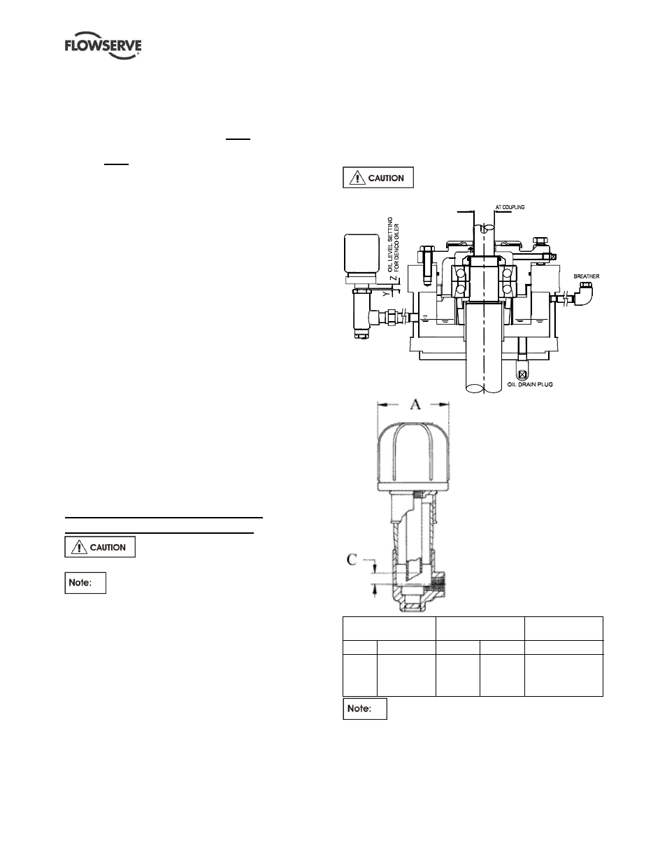
Trico oiler option
Shaft
Denco oiler
setting
Trico oiler
setting
Size
Dia X (mm)
Y (mm)
Z (mm)
C (mm)
1
2
3
4
24
32
42
48
14.5
16.5
17.0
13.5
21.5
23.5
24.0
20.5
12.5
14.5
15.0
11.5
The l
evel setting for a Trico oiler model must
be as the Trico setting in the table.
Pumps with grease lubricated antifriction bearings are
normally supplied fitted with grease nipples and with
pre-greased bearings.
X
Denco oiler