6 electrical connections, 7 protection systems, Electrical connections (4.6) – Flowserve CPXV fitted with Mark 3 ASME hydraulics User Manual
Page 16: Protection systems (4.7)
CPXV with Mark 3 ASME hydraulics ENGLISH 71569291 12-14
Page 16 of 44
flowserve.com
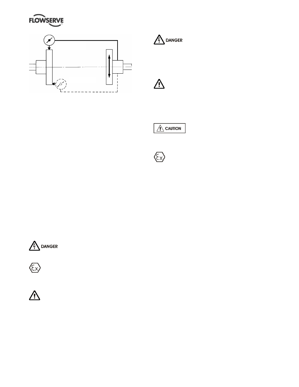
P a r a l l e l
A n g u l a r
Permissible misalignment limits at working temperature:
Parallel alignment
-
0.25 mm (0.010 in.) TIR maximum
Angular alignment
- 0.3 mm (0.012 in.) TIR maximum for couplings
not exceeding 100 mm (4 in.) flange diameter
- 0.5 mm (0.020 in.) TIR maximum for couplings
over 100 mm (4 in.) diameter
Use the lower of the above values and values
indicated in the coupling manual
When checking parallel alignment, the total indicator
read-out (TIR) shown is twice the value of the actual
shaft displacement.
If alignment needs to be adjusted, a small amount of
adjustment of the motor is available within the motor
spigot but alignment is generally achieved
automatically on assembly. Larger motors always
require re-adjustment.
If it is not possible to achieve the alignment accuracy
defined, it may be an indication that the pump has not
been installed or handled correctly.
4.6 Electrical connections
Electrical connections must be made
by a qualified Electrician in accordance with relevant
local national and international regulations.
It is important to be aware of the EUROPEAN
DIRECTIVE on potentially explosive areas where
compliance with IEC60079-14 is an additional
requirement for making electrical connections.
It is important to be aware of the EUROPEAN
DIRECTIVE on electromagnetic compatibility when
wiring up and installing equipment on site. Attention
must be paid to ensure that the techniques used during
wiring/installation do not increase electromagnetic
emissions or decrease the electromagnetic immunity of
the equipment, wiring or any connected devices. If in
any doubt contact Flowserve for advice.
The motor must be wired up in
accordance with the motor manufacturer's
instructions (normally supplied within the terminal
box) including any temperature, earth leakage,
current and other protective devices as appropriate.
The identification nameplate should be checked to
ensure the power supply is appropriate.
A device to provide emergency stopping must
be fitted. If not supplied pre-wired to the pump unit,
the controller/starter electrical details will also be
supplied within the controller/starter.
For electrical details on pump sets with controllers
see the separate wiring diagram.
See section 5.4, Direction of rotation
before connecting the motor to the electrical supply.
4.7 Protection systems
The following protection systems are
recommended but are mandatory if the pump is
installed in a potentially explosive area or is handling
a hazardous liquid. If in any doubt consult Flowserve.
If there is any possibility of the system allowing the
pump to run against a closed valve or below
minimum continuous safe flow a protection device
must be installed to ensure the temperature of the
liquid does not rise to an unsafe level.
If leakage of product from the pump or its associated
sealing system can cause a hazard it is recommended
that an appropriate leakage detection system is installed.
To prevent thrust bearing damage becoming a safety
hazard it is recommended that monitoring of vibration
is carried out.
Where there is the potential hazard of a loss of a seal
barrier fluid the barrier fluid sustem must be monitored.
Where there is a risk that the external flush to a seal or
bearing could fail, for example by freezing, blocking by
debris or loss of supply pressure, then the flow must be
monitored.
Where there is product flush via filters then flow must
be monitored.
Visual indicators are suitable when equipment is
regularly inspected, but sensors connected to the pump
control system must be used if the pump runs remotely.