Flowserve CPXVC User Manual
Page 21
CPXVC USER INSTRUCTIONS ENGLISH 26999930 03-11
Page 21 of 32
flowserve.com
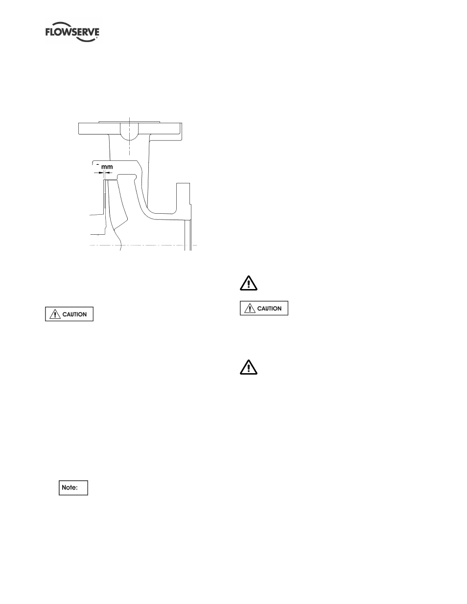
6.7 Setting impeller clearance
This procedure may be required after the pump has
been dismantled or a different clearance is required.
The impeller rear clearance is the setting. Set the
back clearance to 1 mm (0.04 in.), as shown in the
following illustration:
a) Before carrying out this procedure ensure that
any mechanical seal(s) fitted can tolerate a
change in their axial setting, otherwise it will be
necessary to dismantle the unit and reset the
seal axial position after adjusting the impeller
back clearance.
Some mechanical seal types may be
impaired if moved more than 0.5 mm (0.02 in.) from
their nominal setting.
b) Disconnect the coupling if it has limited axial
flexibility.
c) Record the gap between the bearing carrier
[3240] and stool [3160] using feeler gauges.
d) The impeller does not have a fine front clearance
setting and adjustment of the impeller is not
normally required
e) Loosen the bearing carrier nuts and screws
[6570.6] and back off the bearing carrier jacking
screws by
1 mm (0.04 in).
f)
Tighten the bearing carrier screws [6570.5] evenly,
pushing the bearing carrier away from the soleplate,
until the impeller contacts the cover. Turn the shaft
[2100], during this procedure, until a detectable rub
is obtained. This is the zero clearance position.
The shaft must be turned in the direction
indicated on the casing and soleplate.
g) Set a dial indicator to zero on the shaft end or
measure the bearing carrier [3240] to stool [3160]
gap and record the measurement.
h) Slacken the bearing carrier [6570.5] screws
evenly (about one flat at a time) until the dial
i)
indicator or feeler gauge shows the correct
impeller clearance from the zero clearance
position.
j)
Evenly tighten the bearing carrier screws [6570.6]
keeping the dial indicator or feeler gauges reading
the correct setting. Then tighten the hexagon nuts
[6580.3] to lock the jacking screws in position.
k) Compare the original and final gaps between the
bearing carrier and soleplate to check if the
movement of the shaft has exceeded the seal
capability (over/under compression of the seal).
Re-position the seal to correct this.
l)
Check that the shaft can turn freely without binding.
m) If a cartridge seal is fitted, reset it at this point.
n) Ensure the coupling distance between shaft ends
(DBSE) is correct. Reset/re-align if necessary.
6.8 Renewal clearances
As wear takes place between the impeller and cover
[1220] the overall efficiency of the pump set will
decrease. To maintain optimum efficiency it is
recommended that the clearance shown in section
6.7, Setting impeller clearance, is maintained.
6.9 Disassembly
Refer to Safety section 1.6 before dismantling
the pump.
Before dismantling the pump for
overhaul, ensure genuine Flowserve replacement
parts are available.
Refer to sectional drawings for part numbers and
identification. See section 8, Parts lists and drawings.
For pumps with heating jackets, ensure that the
pump is cooled down correctly and sufficiently before
handling. After evacuating the tank and shutting off
the pump, the pumped liquid flows down through the
pump into the sump. After approximately 30 minutes
the heating steam line should be closed.
6.9.1
Pump disassembly
a) Disconnect all auxiliary pipes and tubes where
applicable.
b) Disconnect all discharge and auxiliary pipework.
c) Remove coupling guard [7450], disconnect
coupling [7000] and remove motor [8100].
d) Remove nuts securing soleplate to foundations
and lift the complete unit clear.
e) Record the gap between bearing carrier [3240]
and soleplate [6140] so that this setting can be
used during workshop assembly.
f)
Remove suction tail pipe and/or strainer [9140 /
6531] if fitted.