Flowserve CPXVC User Manual
Page 14
CPXVC USER INSTRUCTIONS ENGLISH 26999930 03-11
Page 14 of 32
flowserve.com
These flanges are located on the upper side of the
soleplate. A flanged steam valve should be provided
at the steam inlet and outlet for control of the steam
supply.
4.5.5
Final checks
Check the tightness of all bolts in the suction and
discharge pipework. Check also the tightness of all
foundation bolts.
After connecting piping to the pump, rotate the shaft
several times by hand to ensure there is no binding
and all parts are free.
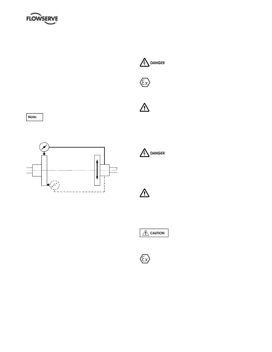
Recheck the flexible element coupling is aligned with
the permitted limits.
Where there is the option of an additional
rigid coupling below the thrust bearing, above the
mechanical seal, this has full metal to metal joints
which does not permit its adjustment.
Parallel
Angular
For couplings with narrow flanges use a dial indicator
as shown. The alignment values are maximums for
continuous service.
Permissible misalignment limits at working temperature:
•
Parallel alignment
- 0.25 mm (0.010 in.) TIR maximum
•
Angular alignment
- 0.3 mm (0.012 in.) TIR maximum for couplings
not exceeding 100 mm (4 in.) flange diameter
- 0.5 mm (0.020 in.) TIR maximum for couplings
over 100 mm (4 in.) diameter
•
Use the lower of the above values and values
indicated in the coupling manual.
When checking parallel alignment, the total indicator
read-out (TIR) shown is twice the value of the actual
shaft displacement.
If alignment needs to be adjusted, a small amount of
adjustment of the motor is available within the motor
spigot but alignment is generally achieved
automatically on assembly. Larger motors always
require re-adjustment.
If it is not possible to achieve the alignment accuracy
defined, it may be an indication that the pump has not
been installed or handled correctly.
4.6 Electrical connections
Electrical connections must be made by
a qualified Electrician in accordance with relevant
local national and international regulations.
It is important to be aware of the EUROPEAN
DIRECTIVE on potentially explosive areas where
compliance with IEC60079-14 is an additional
requirement for making electrical connections.
It is important to be aware of the EUROPEAN
DIRECTIVE on electromagnetic compatibility when
wiring up and installing equipment on site. Attention
must be paid to ensure that the techniques used during
wiring/installation do not increase electromagnetic
emissions or decrease the electromagnetic immunity of
the equipment, wiring or any connected devices. If in
any doubt contact Flowserve for advice.
The motor must be wired up in
accordance with the motor manufacturer's
instructions (normally supplied within the terminal
box) including any temperature, earth leakage,
current and other protective devices as appropriate.
The identification nameplate should be checked to
ensure the power supply is appropriate.
A device to provide emergency stopping must
be fitted. If not supplied pre-wired to the pump unit,
the controller/starter electrical details will also be
supplied within the controller/starter.
For electrical details on pump sets with controllers
see the separate wiring diagram.
See section 5.4, Direction of rotation
before connecting the motor to the electrical supply.
4.7 Protection systems
The following protection systems are
recommended particularly if the pump is installed in a
potentially explosive area or is handling a hazardous
liquid. If in any doubt consult Flowserve.
If there is any possibility of the system allowing the
pump to run against a closed valve or below
minimum continuous safe flow a protection device
should be installed to ensure the temperature of the
liquid does not rise to an unsafe level.