3 spare parts, 4 recommended spares, 5 tools required – Flowserve CPXVC User Manual
Page 20: 6 casing, seal housing and fastener torques
CPXVC USER INSTRUCTIONS ENGLISH 26999930 03-11
Page 20 of 32
flowserve.com
6.2.2
Periodic inspection (six monthly)
a)
Check foundation bolts for
security of attachment and corrosion.
b) Check pump running records for hourly usage to
determine if bearing lubricant requires changing.
c) The coupling should be checked for correct
alignment and worn driving elements.
d)
Refer to the manuals of any associated
equipment for periodic checks needed.
6.2.3
Re-lubrication
For general guidelines refer to section 5.2.5,
Lubrication schedule.
Lubricant and bearing temperature analysis can be
useful in optimizing lubricant change intervals.
6.2.4
Mechanical seals
When leakage becomes unacceptable the seal will
need replacement.
6.2.5
Gland packing
The stuffing box is normally supplied with a lantern ring
to enable it to be lubricated to the centre of the packing
with the required Molykote 44 Medium or equivalent
grease from a Staufer or equivalent.
6.3 Spare parts
6.3.1
Ordering of spares
Flowserve keeps records of all pumps that have been
supplied. When ordering spares the following
information should be quoted.
1)
Pump serial number.
2)
Pump size.
3)
Part name – taken from section 8.
4)
Part number – taken from section 8.
5)
Number of parts required.
The pump size and serial number are shown on the
pump nameplate.
To ensure continued satisfactory operation,
replacement parts to the original design specification
should be obtained from Flowserve. Any change to
the original design specification (modification or use
of a non-standard part) will invalidate the pump’s
safety certification.
6.3.2
Storage of spares
Spares should be stored in a clean dry area away
from vibration. Inspection and re-treatment of
metallic surfaces (if necessary) with preservative is
recommended at 6 monthly intervals.
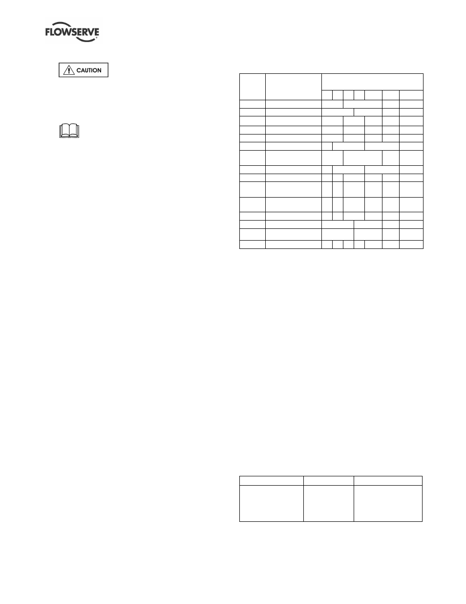
6.4 Recommended spares
(For two years operation - as per VDMA 24296)
Number of pumps
(including stand-by)
Part
no.
Designation
2
3
4
5
6/7
8/9
10(+)
2100
Shaft
1
2
3
30%
2200
Impeller
1
2
3
30%
3011
Radial ball bearing
1
2
3
4
50%
3013
Bearing - thrust
1
2
3
4
50%
3712
Bearing nut
1
2
3
4
50%
4120
Lantern halves #
1
2
3
30%
4130
Gland packing -
complete set #
2
3
4
40%
4200
Mechanical seals # 1
2
3
30%
4305
Lip seal #
4
6
8
9
10
100%
4590.1 *
Pump casing
gasket
4
6
8
9
12
150%
4590.3
Discharge flange
gasket
4
6
8
9
12
150%
4590.2
Impeller gasket
4
6
8
9
12
150%
4610.1
O-ring carrier
2
3
4
50%
4610.3
O-ring soleplate#
2
3
4
50%
-
Power end
-
-
-
-
-
1
2
# When required due to fitting as part of the original build specification.
6.5 Tools required
A typical range of tools that will be required to
maintain these pumps is listed below.
Readily available in standard tool kits, and dependent
on pump size:
•
Open ended spanners (wrenches) to suit up to
M 48 screws/nuts
•
Socket spanners (wrenches), up to M 48 screws
•
Allen keys, up to 10 mm (A/F)
•
Range of screwdrivers
•
Soft mallet
More specialized equipment:
•
Bearing pullers
•
Bearing induction heater
•
Dial test indicator
•
C-spanner (wrench) - for removing shaft nut.
(If difficulties in sourcing are encountered, consult
Flowserve.)
6.6 Casing, seal housing and fastener
torques
Fastener
Screw size
Torque Nm (lbf ft)
All except where
otherwise stated
M8
M10
M12
M16
M20
16 (12)
25 (18)
35 (26)
80 (59)
130 (96)