Flowserve Type R User Manual
Page 35
R and RX SLURRY Pump USER INSTRUCTIONS ENGLISH
71569242 03-11 (E)
Page 35 of 56
flowserve.com
®
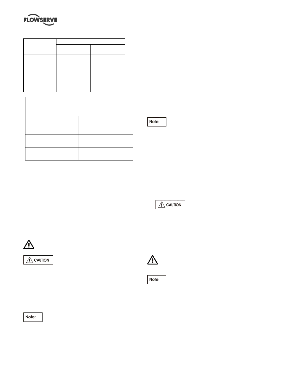
6.6 Fastener torques
Bolt size
Torque Nm (lbft)
Pump feet
fasteners
All other
fasteners
M 16 (⅝ in.)
M 20 (¾ in.)
M 24 (⅞ in.)
M 27 (1 in.)
M 30 (1⅛ in.)
M 36 (1⅜ in.)
M 42 (1⅝ in.)
M 48 (1⅞ in.)
170 (125)
340 (250)
590 (435)
770 (570)
1 100 (810)
1 840 (1 350)
2 000 (1 475)
2 240 (1 650)
84 (62)
165 (120)
285 (210)
375 (275)
540 (400)
900 (660)
1 410 (1 040)
2 060 (1 500)
TIGHTENING TORQUE
FOR STAINLESS STEEL STUDS
WITH LUBRICATED THREADS
THREAD SIZE
TIGHTENING TORQUE
Nm ft.
lbs.
M10x1.5 (3/8–16UNC)
13
10
M12x1.75 (1/2–13UNC)
27
20
M16X2 (5/8-11UNC)
60
45
M20x2.5 (¾-10UNC)
100
75
6.7 Renewal clearances
As wear takes place between the impeller and casing
liners the overall efficiency of the pump set will
decrease. To maintain optimum performance it is
recommended that the impeller clearance be reset.
Some services will dictate that adjustments be
performed regularly. Excessive clearance will induce
greater recirculation and accelerate the rate of wear.
The liners or impeller must be replaced when there is
no more adjustment capability in the bearing housing.
Leakage at the liner mounting studs and/or flange
joints may indicate that the liner has holed.
6.8 Disassembly
Refer to section 1.6, Safety, before dismantling
the pump.
Before dismantling the pump for
overhaul, ensure genuine Flowserve replacement
parts are available.
To disassemble the pump consult the sectional
drawings, see section 8, Parts list and drawings.
6.8.1 Rotating
Element
The following procedure is recommended for removing
and disassembling the rotating assembly.
Note that the replacement gaskets and
similar consumable materials should be available
since they will be required for reassembly.
a) Isolate motor and lock off electrical supply in
accordance with local regulations.
b) Isolate suction and discharge valves.
c) Remove
guards
d) Disconnect the coupling halves or remove belts
from sheaves.
e) Drain pump casing. Remove any auxiliary piping
if applicable.
f)
Disconnect stuffing box, cooling water and auxiliary
piping
.
g)
Drain the oil from the bearing frame [3130] if bearing
frame is being dismantled.
h)
Disconnect pump from piping and remove spool
pieces as necessary.
i) Remove pump from baseplate to work on bearing
frame.
For pumps fitted with an overhead motor
mount it is suggested that the motor be removed.
The remaining steps assume that the pump has been
removed.
j) Remove suction side casing [1211] from
Glandside casing [1212].
6.8.1.1 Expeller Pumps only
a) Release the thrust bearing housing [3230] hold down
bolts and jam nuts. While rotating the pump shaft
[2110] by hand, tighten the three jacking screws
evenly until the impeller [2] lightly clamp the expeller
housing [4110]. This will simplify withdrawal of the
rotating element from the casing.
Excessive clamping force could
damage bearing races.
Rotating the shaft helps to clear away solids which
may be trapped between the impeller and expeller
housing.
b) Unfasten glandside casing [1212} from the pedestal
[3120].
c) Remove glandside casing [1212].
d) Clamp the expeller Housing to the pedestal to
prevent it from accidentally coming loose.
6.8.1.2 Impeller (all pumps)
The impeller is threaded to the shaft and has been self
tightened to the shaft sleeve. To unscrew the impeller
the torque must be broken. It will be necessary to
either block the impeller or shaft at the drive-end. A
fixture similar to that shown in the sketch may be
used. To unscrew the impeller
the shaft must be
turned counter-clockwise.