4 materials of construction, 5 performance and operating limits – Flowserve WDX User Manual
Page 14
WDX USER INSTRUCTIONS ENGLISH 71576322 06-05
Page 14 of 46
®
3.3.5 Pump bearings and lubrication
WDX pumps are designed so the antifriction bearings
may be either oil or grease lubricated.
WDXE and WDXS have product lubricated line
bearings with sleeve and bushing made of silicon
carbide.
Bearing isolators or stationary labyrinths may be fitted
as an option in the bearing covers to protect the
bearings.
3.3.6 Bearing housing
Grease nipples enable grease lubricated bearings to
be replenished between major service intervals. For
oil-lubricated bearings, a constant level oiler is fitted.
3.3.7 Stuffing box housing
The stuffing box housing has a spigot (rabbet) fit
between the pump casing and bearing housing for
optimum concentricity. The design enables a number
of sealing options to be fitted.
3.3.8 Shaft seal
The mechanical seal(s) attached to the pump shaft
seals the pumped liquid from the environment.
Stuffing boxes have been designed for component or
cartridge seals. Gland packing may be fitted as an
option.
3.3.9 Driver
The driver is normally an electric motor. Different drive
configurations may be fitted such as internal combustion
engines, turbines, hydraulic motors etc driving via
couplings, belts, gearboxes, drive shafts etc.
3.3.10 Accessories
Accessories may be fitted when specified by the
customer.
3.4 Materials of construction
Material
column
Casing
Impeller
Shaf t
M2
Cast iron
Cast iron
Chrome steel
M3
Carbon s teel
Cast iron
Chrome steel
M4
Carbon s teel
Stainless
steel
Chrome steel
M5
Chrome steel
Stainless
steel
Chrome steel
M6
Duplex
stainless s teel
Stainless
steel
Duplex
stainless s teel
M7
Stainless steel
Stainless
steel
Duplex
stainless s teel
3.5 Performance and operating limits
This product has been selected to meet the
specifications of your purchase order. See the
nameplate and section 1.5.
The maximum allowable speed for cast iron
impellers is 3600 RPM and for steel impellers is 4000
RPM.
3.5.1 Minimal flow
20 % of BEP up to 280° F (140 °C)
25 % of BEP between 280 °F (140 °C) and 410 °F
(210 °C)
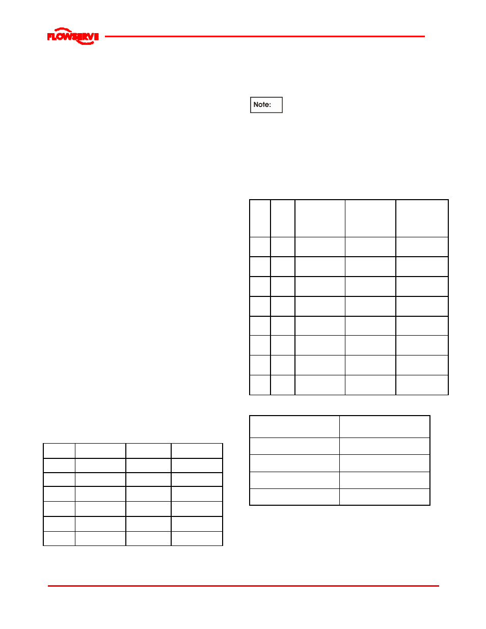
3.5.2 Clearance data
Size
Mat
Nominal wear
ring clearance
min/max
mm (inch)
Nominal
Interstage
clearance
min/max
mm (inch)
Nominal
Balance drum
clearance
min/max
mm (inch)
1.5
M2
M3
0.170/ 0.259
(0.0067/ 0.0102)
0.170/ 0.259
(0.0067/ 0.0102)
0.150/ 0.226
(0.0059/ 0.0089)
1.5
M4 to
M7
0.320/ 0.409
(0.0126/ 0.0161)
0.170/ 0.259
(0.0067/ 0.0102)
0.300/ 0.376
(0.0118/ 0.0148)
2
M2
M3
0.170/ 0.259
(0.0067/ 0.0102)
0.170/ 0.259
(0.0067/ 0.0102)
0.170/ 0.259
(0.0067/ 0.0102)
2
M4 to
M7
0.330/ 0.419
(0.0130/ 0.0165)
0.170/ 0.259
(0.0067/ 0.0102)
0.470/ 0.559
(0.0185/ 0.0220)
3
M2
M3
0.200/ 0.303
(0.0079/ 0.0119)
0.200/ 0.303
(0.0079/ 0.0119)
0.170/ 0.259
(0.0067/ 0.0102)
3
M4 to
M7
0.360/ 0.463
(0.0142/ 0.0182)
0.200/ 0.303
(0.0079/ 0.0119)
0.480/ 0.569
(0.0189/ 0.0224)
4
M2
M3
0.200/ 0.303
(0.0079/ 0.0119)
0.200/ 0.303
(0.0079/ 0.0119)
0.180/ 0.269
(0.0071/ 0.0106)
4
M4 to
M7
0.410/ 0.513
(0.0161/ 0.0202)
0.200/ 0.303
(0.0079/ 0.0119)
0.500/ 0.603
(0.0197/ 0.0237)
3.5.3 Sleeve bearing clearance (WDXE/S)
Pump size
Diametral cl earance
min/max
mm (inch)
1.5 WDX
0.007 - 0. 041
(0.0003 - 0.0016)
2 WDX
0.007 - 0. 041
(0.0003 - 0.0016)
3 WDX
0.007 - 0. 041
(0.0003 - 0.0016)
4 WDX
0.007 - 0. 041
(0.0003 - 0.0016)
3.5.4 Bearing bushings
Interstage bearing bushings can be mounted on the
pump. Their number and location depend on the
material chosen and the number of stages of the
pump. For further information, see general
arrangement drawing of the pump.