First Co FRR User Manual
Page 4
4
Route field power supply to the junction box at the front of the return air opening. Install in accordance with the unit wiring
diagram and all applicable codes. Standard controls are mounted on a 4” x 4” square junction box on the front of the cabinet
where provision has been made for sheet rock installation..
PROCEDURE 4 - FRAMING AND FINISHING
Models RR, RM and RS all have factory enclosures suitable for normally accepted wall coverings. If sheetrock is the
covering of choice then low profile sheetmetal screws are needed.
CAUTION: Do not apply sheetmetal screws or nails where they can penetrate the coil, risers, drain pan or electrical
conduits. If possible secure at the corners of the cabinet once component placement is verified.
Ensure that sheetrock dust and debris do not enter the unit during construction and finishing. This will compromise the
performance, general cleanliness of the cabinet and draining ability.
Use care when making openings for the supply grilles to avoid debris penetration into the cabinet. It is not likely but
possible to contact the power cables in the corners where the conduit knockouts are placed, so take care to avoid these as
well. Once done cover these openings so as to avoid wall finishings from being sprayed or otherwise flung into the cabinet.
WARNING:
The manufacturer does not warrant equipment subjected to abuse. Metal chips, dust, drywall
tape, paint over spray, etc. can void warranties and liability for equipment failure, personal injury and
property damage.
PROCEDURE 3 – ELECTRICAL CONNECTIONS
NOTE:
Before proceeding with electrical connections, make certain that supply voltage, frequency, and phase are as
specified on unit rating plate. Be sure that electrical service provided by the utility is sufficient to handle the additional load
imposed by this equipment. See unit wiring label for proper field high and low voltage wiring. Make all electrical connec-
tions in accordance with NEC and any local codes or ordinances that may apply. Use copper wire only.
Line-Voltage Connections
All units have wiring diagrams and nameplate data to provide information required for necessary field wiring.
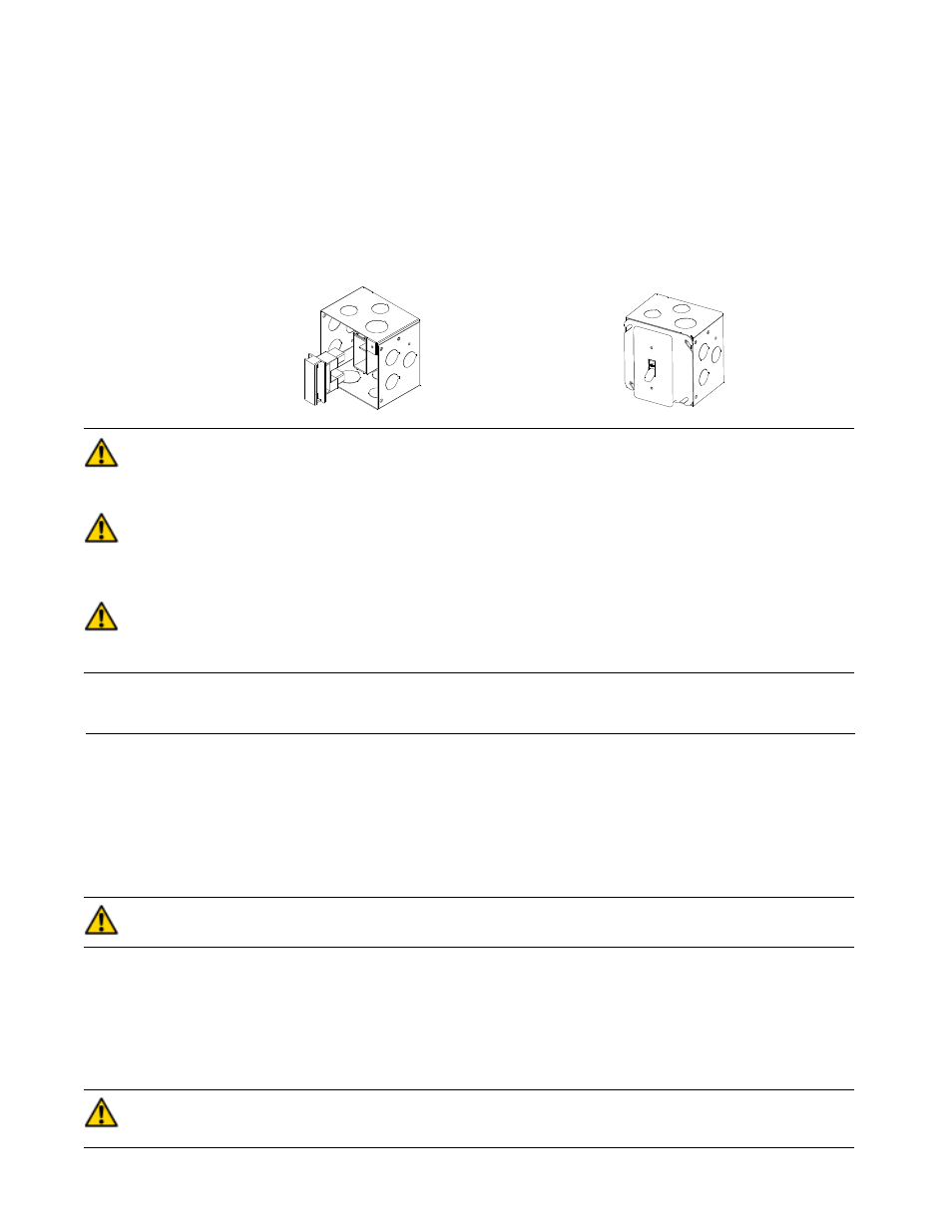
A 4” x 4” electrical box is standard on all units for proper connection of power supply.
Unit must be permanently grounded in accordance with NEC and local codes.
Check all factory wiring per unit wiring diagram and inspect factory wiring connections to be sure none were loosened in
transit or installation.
J-Box with disconnect
J-Box with toggle
120V / 240V w/ electric
switch. Units w/o
heat
electric heat & 277V
w/ electric heat
DANGER:
Service and maintenance to internal components and wiring must not be performed until the
main disconnect switch is turned off. Failure to do so will result in electrical shock causing personal injury
or death.
WARNING:
Any remote mounted devices such as thermostats that have been furnished by the manufac-
turer for field installation must be wired in strict accordance with the wiring diagram that is supplied with
the unit. Failure to do so could result in electrical shock causing personal injury, death or damage to
components and will void all warranties
WARNING:
The cabinet must have an uninterrupted or unbroken ground according to NEC, ANSI/NFPA 70
and local codes to minimize personal injury if an electrical fault should occur. The ground may consist of
electrical wire or metal conduit when installed in accordance with existing electrical codes. (See Ground/
Conduit Note below.) Failure to follow this warning could result in an electrical shock, fire, or death.
NOTE:
Use agency listed conduit and conduit connector to connect supply wire(s) to unit and obtain proper grounding. If
conduit connection uses reducing washers, a separate ground wire must be used.