First Co SPXA (cooling with electric heat) User Manual
Page 4
4
directions furnished with the
thermostat. The thermostat should be
located on an inside wall where it will
not be affected by drafts, sunlight or
any other heat producing appliances.
Connect thermostat wires to the
thermostat following the wiring diagram
attached to the unit.
13. Connect low voltage thermostat
wires from remote thermostat to the
SPX unit (Fig. 3).
14. Install ductwork onto unit dis-
charge and ensure that the connec-
tion is leak free. A flexible boot con-
nection may be desirable to provide
for more convenient installation and
removal of the SPX unit.
15. Replace the rear access panel
and disconnect.
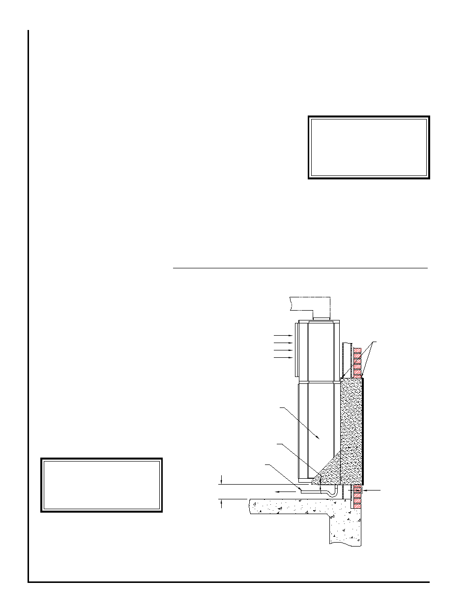
CONDENSATE DRAIN
The SPX is designed so that the
wall sleeve is the principle drain pan.
Drain tubing is factory installed which
drains evaporator condensate
through the bottom of the unit which
then is allowed to drain into the wall
sleeve pan.
Note: When preparing unit for
installation check to ensure that the
drain tubing from the evaporator is
securely attached to the copper nipple
in the pan under the compressor. The
wall sleeve has a 3/4 NPT nipple
located in the bottom for connection
to a drain (Fig. 4). A trap may be
required in the condensate drain line
to prevent sewer gas from escaping
into the room.
Prior to unit installation ensure that
the drain is unobstructed and leak
free.
AIR FILTER
All indoor return air must be filtered.
The preferred methods are:
1. Use the factory supplied filter kit
which attaches to the inlet of the
evaporator and accepts a
20” x 24” x 1” field supplied throwaway
type filter.
2. Use the filter kit supplied with the
access panel which accepts a
20” x 20” x 1” throwaway type filter.
3. Install a filter in the return grille
mounted in the wall. Any field
installation of an air filter means must
provide for use of a disposable filter
which is no smaller than the face area
of the evaporator coil.
The air filter should be cleaned or
replaced every 30 days or more
frequently if severe conditions exist.
EVAPORATOR BLOWER
SPEEDS
The unit contains a direct drive,
multi-speed blower. The proper speeds
have been preset at the factory for
heating and cooling. Refer to wiring
diagram for recommended blower
speeds for specific models.
OPERATING
INSTRUCTIONS
Operation of the unit is automatic
and will provide heating and cooling
depending on the setting of the
thermostat.
Note: Loosen compressor mounting
nuts if unit vibration is excessive.
SYSTEM CHECK
Cooling/Electric Heat Units
1. Set thermostat system switch to
“Off” position and fan switch to “Auto”
position. Apply power to the SPX unit.
Figure 4 - Side View
Return
Air
6” min.
To Condensate
Drain
SPX Unit
1/4” min.
1/2 Bubble
Sealant
****** WARNING ******
SPX units must not be operated
under any circumstances with-
out an air filter in place.
****** WARNING ******
All panels must be installed
and disconnect switch must
be in place before operating
unit.