First Co SPXA (cooling with electric heat) User Manual
Page 3
3
INSTALLATION
1. Ensure that properly sized duct
work is in place to mate to the supply
connection on the SPX.
2. Remove the two clips holding the
unit to the shipping pallet and remove
unit from the shipping pallet.
3. Before setting unit into closet,
remove upper side access panels and
inspect the evaporator blower to
ensure that the wheel turns freely
without rubbing on the housing.
Note: Remove the styrofoam ship-
ping block supporting the blower
assembly.
Replace upper access doors prior to
completing installation.
4. Remove disconnect and the rear
access door to get to the loose items
described in the packing list. Check
all electrical connections and check
the condenser fan to see that it turns
freely. Note nameplate voltage, am-
perage and fuse size for proper power
supply.
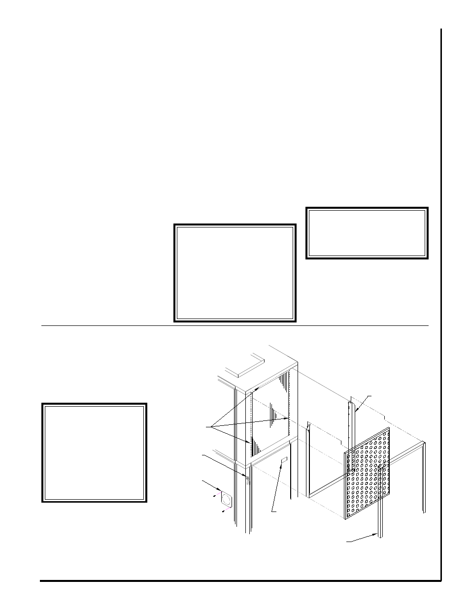
5. The SPX is equipped with bend out
flanges (Fig. 3), next to the evaporator
coil, for the purpose of attaching a
return air duct. If ducted return air is
required these flanges must be bent
90 degrees away from the face of the
evaporator coil along the perforations.
Note: If the unit will not be connected
to a fixed return duct these flanges
must be broken off of the unit.
6. If an air filter is to be applied to the
unit install the filter bracket by insert-
ing the tab portion of the rack between
the insulation and middle plate under
the drain pan (Fig. 3). Place a 20” x
24” x 1” filter into the filter rack. In-
sert the two tabs on the filter clip into
the slots above the evaporator and
hook the front flange under the filter
flange to hold the filter in place.
7. A fresh air make up vent is located
on the lower left side door (Fig. 3).
Remove one screw and rotate the
plate to expose the desired amount
of vent opening. Replace the screw to
hold the door in desired location.
8. Ensure that the wall sleeve is
installed squarely and is secure before
installing the unit.
Note: After removing the construction
debris guard, inspect the sleeve seal,
which is supplied with the sleeve, to
ensure that it is properly secured and
aligned (Fig. 2). Use a high grade non-
hardening sealant to close any gaps
that may exist between the seal and
the wall of the sleeve.
9. After the seal is inspected, lift the
unit onto the base of the sleeve and
slide the unit forward to engage the
seal. The unit is fully engaged when
the upper housing of the SPX is 1/2”
away from the top inside edge of the
sleeve.
10. Check that the unit is completely
seated on all four sides against the
wall sleeve seals.
If necessary seal any openings that
may exist.
11. Connect properly sized electrical
service to the disconnect block.
12. Install a factory approved or
equivalent thermostat according to
Figure 3 - Filter Bracket Detail
Filter
Bracket
Filter
Retainer
Electrical
Disconnect
Ducted Return
Air Flanges
Thermostat
Connection
Fresh Air
Vent
***** WARNING *****
SPX Heat Pump units op-
erate with the reversing
valve energized in the
HEATING mode. The
thermostat must be wired
or configured accord-
ingly or the unit will not
operate properly.
****** WARNING ******
After removing the construc-
tion debris guard, check the
bottom of the pan to ensure
that it is sloped one half
bubble toward the outside.
Ensure that the bottom of the
pan and drain are clear of ob-
struction and operational.
****** WARNING ******
If unit is not sealed com-
pletely, water and/or outside
air will infiltrate into the closet.
Air
Filter