First Co SPXA (cooling with electric heat) User Manual
Page 2
2
removal of the unit should repair and
inspection be required.
For installations requiring access
panels refer to unit brochure for panel
dimensions.
WALL SLEEVE
INSTALLATION
Refer to installation instructions
packed with wall sleeve to assemble
and mount it in the wall. Before unit
installation, make sure sleeve
components are not damaged, drain
line is unobstructed and leak free.
Check all seals to ensure that they are
in position and un-damaged. Ensure
that the bottom of the wall sleeve is
pitched 1/2 bubble toward the outside
of the building so that rain water will
drain to the outside (Fig. 4). Securely
fasten the Architectural grille to the
front of the sleeve using the supplied
hardware.
ELECTRICAL
All wiring must comply with local
and national code requirements. Any
alteration of the internal wiring will void
UL certification and manufacturer’s
warranty.
Nameplate data indicates the
operating voltage, phase, ampacity,
maximum over current protection and
minimum voltage. Units must never
be installed or operated where voltage
exceeds the nameplate voltage by
more than 10%. Failure of the
compressor as a result of operation
with improper voltage voids the
compressor replacement warranty.
The unit comes with a factory
supplied disconnect, however, the
contractor is responsible for providing
over current protection on the branch
circuit. Refer to the unit wiring diagram
for single point electrical connection.
These units are provided with a
Class 2 transformer for 24 volt control
circuits. Should any add-on
equipment also have a Class 2
transformer furnished, care must be
taken to prevent interconnecting
outputs of the two transformers by
using a thermostat with isolating
contacts.
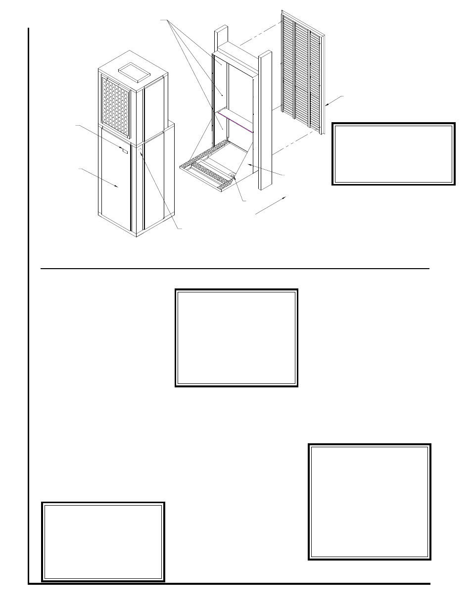
Figure 2 - General Assembly
Approximate
Fastener
Locations
Architectural
Grille
Wall Sleeve
Outside
Electrical Service
Knock-out
Electrical
Disconnect
****** WARNING ******
Make sure a high grade non-
hardening sealant approved for
exterior use has been applied
between edge of the sleeve and
the structure, on the inside and
outside walls, to prevent air
and water from migrating
inside (Fig. 4).
Rear Access
Panel
****** WARNING ******
There must be a minimum 3"
clearance maintained around
the SPX chassis on all sides for
adequate airflow to achieve
optimum performance. These
guidelines give minimum spac-
ing requirements only. It is
acceptable to go beyond these
limits at any time.
Drain
****** WARNING ******
After sleeve installation ensure
that the sleeve seal is in contact
with the sleeve sides. Any air
gaps must be sealed or
outdoor air and/or water
leakage will occur.
****** WARNING ******
Architectural Grille must be
installed prior to the
installation of the SPX unit into
the sleeve.