Installation (cont.) – Fire Magic 3049 Aurora Infrared Burner Kit Installation User Manual
Page 3
REV 3 - 1302260945
L-C2-280
3
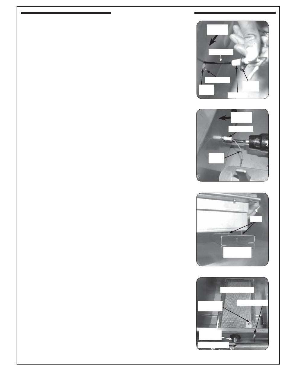
INSTALLING THE NEW INFRARED BURNER
1. Locate the new ignitor wire with the insulator attached and thread
the wire end through the hole in the oven fi re wall left by the old
ignitor, from the oven side as shown in Fig. 3-1. Continue to thread
the wire end through the insulator tube in the manifold fi re wall and
through the slot in the heat shield, then route it toward the ignitor
module on the right. (Hint: wrap around existing wire bundle.)
2. Attach the other end of the new ignitor wire (the insulated end) to
any male connector on the back of the ignitor module (reference
Fig. 2-5).
Important: Test all electrodes for spark before securing the control
panel to the frame (see also the section on battery
replacement in your owners manual).
Note: The wires can be plugged into any terminal.
3. Attach the insulated portion of the ignitor wire to the inside of the
oven fi re wall by placing the screw (included) through the bracket
hole and into the hole in the fi re wall (see Fig. 3-1 and Fig. 3-2).
4. Place the new infrared burner gas intake tube in the hole in the
oven fi re wall and over the orifi ce fi tting, sliding it forward from
behind the control panel frame, so the orifi ce is centered inside
the burner gas tube. Set it gently onto the rear burner support,
making sure the tabs on the back burner bottom each fi t through
their respective slots in the rear burner support. This is critical to
the safe function of the grill. (See Fig. 3-3 and Fig. 3-4.)
Fig. 3-1 Screw the new wire to the fi re wall
Front fi re
wall
Ignitor wire
Ignitor
hole
Screw hole
Bracket
hole
Insulator
Fig. 3-2 Screw the new wire to the fi re wall
To front
fi re wall
Insulator
Ignitor
wire
Fig. 3-3 Sliding tabs into support
Rear burner
support
Tabs
Fig. 3-4 Infrared burner installed
Ignitor
electrodes
Infrared burner
Gas intake
tube
Gas manifold
Wire insulator
INSTALLATION (cont.)