Assembly and installation (cont.) – Fire Magic DC430-XXR-75SM Island Enclosure User Manual
Page 8
8
REV 6 - 1409101305
L-C2-306
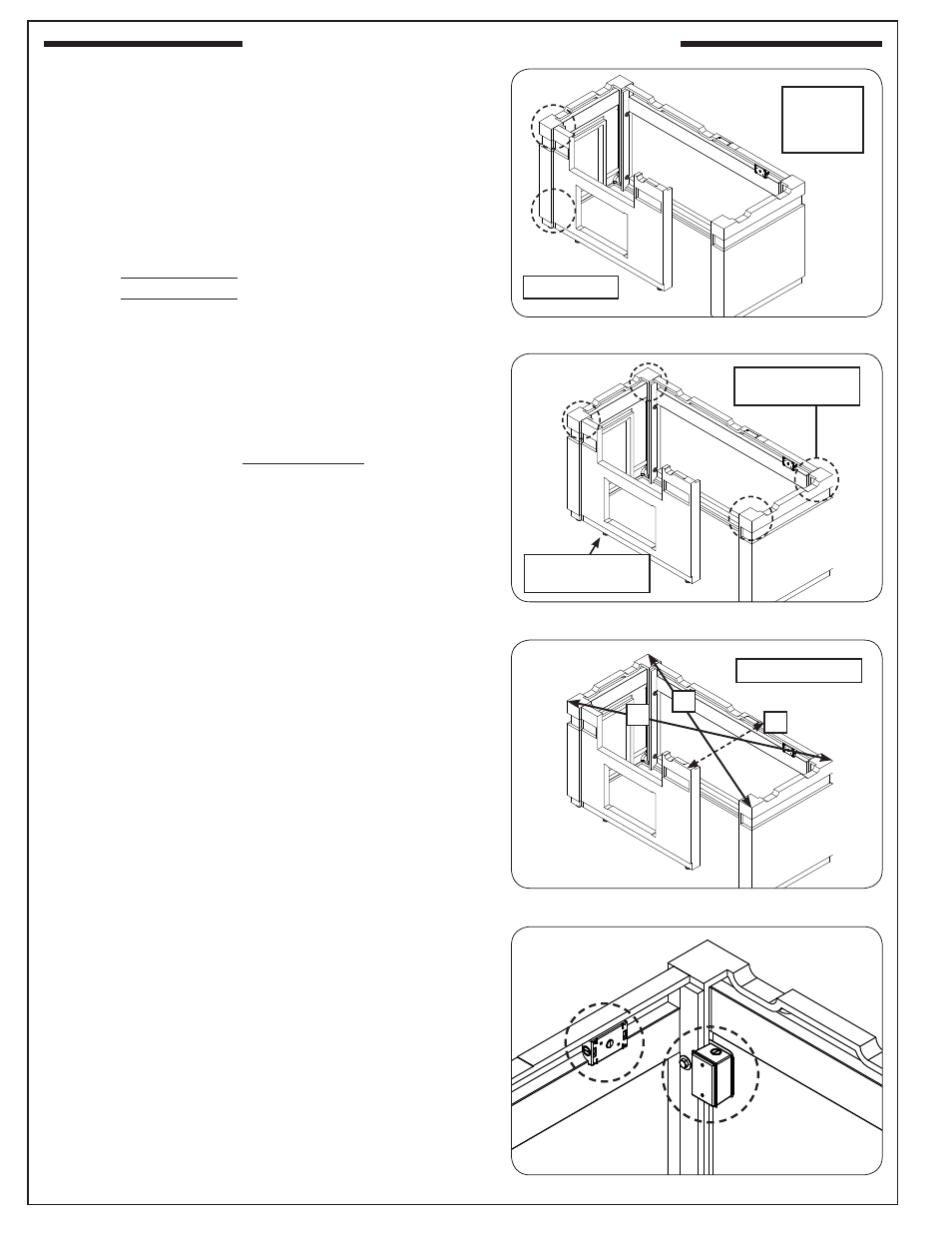
ASSEMBLY AND INSTALLATION (Cont.)
5. Orient the front wall and repeat the hardware installation
process (on left side only). See Fig. 8-1.
6. Use the level to ensure the top surfaces of the assembly
are level. The levelers at the bottom of the island may
be adjusted as needed. See Fig. 8-2.
7. Check for squareness of the island.
a. Measure the X outer dimension, see Fig. 8-3. It should
be approximately:
• DC430 models: 79
3
/
4
"
• DC790 models: 108
3
/
4
"
b. Measure the Y outer dimension, see Fig. 8-3.
Carefully adjust the side walls as needed to ensure
the X & Y dimensions are equal. (The fi nal dimension
may slightly vary from that mentioned in step a.)
c. Measure the Z outer dimension, see Fig. 8-3. It should
be approximately 30
1
/
2
".
8. Once the assembly is level and square, use the two
3
/
4
"
open end wrenches (or equivalent) to fully tighten all
hardware. DO NOT OVERTIGHTEN.
Note: Tightening of the hardware may slightly alter the
setup. Check once more to ensure the island is level
and square, and adjust if needed.
Install Electrical
Have a licensed electrician route the electrical setup for
your island. Two outlet boxes are available. The primary box
is located on the interior of the right wall. An additional box
exists at the top of the rear wall. See Fig. 8-4.
Your installation may vary. Observe all local codes.
Fig. 8-1 Assemble front wall
Fig. 8-2 Level assembly
Fig. 8-3 Square unit (then tighten bolts)
Adjust all levelers
as needed
Ensure all top
surfaces are level
Fig. 8-4 Install electrical (as needed)
Y
X
Z
(outer dimensions)
(hand tighten)
Hardware:
Bolts x 2
Nuts x 2
Washers x 4