Installation (cont.) – Fire Magic Deluxe Post Barbecue Patio Mount User Manual
Page 7
7
CONNECTING TO THE GAS SUPPLY
Always ensure the orifi ces and regulator are set
for the gas type your unit is to be installed to.
This post barbecue is capable of connecting to the
gas supply in a few different ways. The connection
can be made inside the post, under the post base,
or out the back of the post.
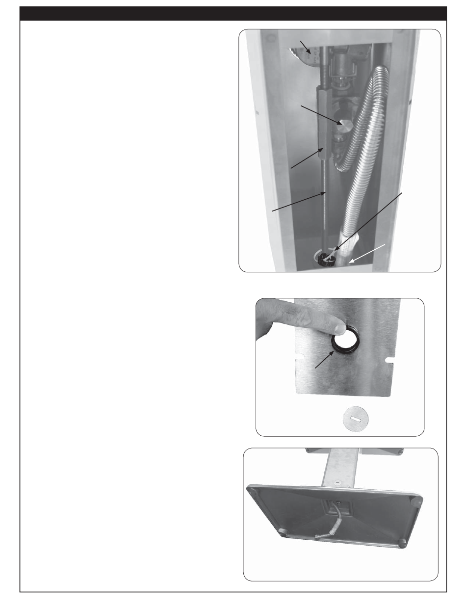
The gas must be hooked up so that it passes through
the regulator and timer located in the post. To access;
unscrew and remove the access plate in the back
of the post using a No. 3 Phillips-head screwdriver.
Retain the screws.
To connect through the post, remove the knock-out
disk at the bottom of the access plate with a large
standard screwdriver by inserting the screwdriver
into the notch provided in the center of the knock-
out. Remove the plastic grommet fastened to the
inside of the post and insert it into the newly created
opening prior to passing the gas connection through
the opening.
To connect through the post base, run the gas
connection through the hole provided in the center
of the post base.
Connect the supplied
1
/
2
" pipe adapter fi tting to the
gas supply stub. Use pipe joint compound that is
resistant to all gasses on the male pipe fi tting. Connect
the fl ex connector to the adapter. Tighten securely.
Turn all burner valves to the OFF position. Turn
the gas supply on. Then carefully check all gas
connections for leaks with a brush and soapy water
before lighting. NEVER USE A MATCH OR OPEN
FLAME TO TEST FOR LEAKS.
When fi nished, replace access plate and tighten the
four screws provided.
SECURING THE POST BARBECUE
Important: BEFORE USE, the patio mount base
must be securely fastened to a stable,
level surface to ensure the grill remains
fi xed and upright at all times.
Locate the patio mount base in the planned grill
location and mark the 4 holes. Drill the marked holes
to a
1
/
2
" diameter x 1
1
/
2
" depth. Insert the lag shields
(see PARTS LIST) into the holes, being sure that
they are fl ush with the ground.
Align the holes on the patio mount base over the lag
shields in the ground. Secure the base with the lag
screws (see PARTS LIST) using a
7
/
16
" nut driver.
Access plate
Knock-out
Grommet (installed)
Fig. 7-4
Fig. 7-3
Post (access panel removed)
Flex connector
through hole in
base
Back of timer valve
Grommet
attached with
tie
Location of
regulator
Fig.
7-2
Adjustable
Nut
Tension
Bolt
INSTALLATION (Cont.)