Checking/converting the burner orifices – Fire Magic Deluxe Post Barbecue Patio Mount User Manual
Page 12
12
CHECKING/CONVERTING THE BURNER ORIFICES
MAIN BURNER ORIFICE SIZE CHECKING/
CONVERSION
Before beginning, make sure you have the proper
tools for the task.
This task requires:
•
a Phillips-head screwdriver (2 pt)
•
a deep
3
/
8
"
nut driver with a spacer (#6 nut)
1. Remove both grills from over the main burners
and set them aside.
2. Remove both fl avor grids from above the main
burners and set them aside.
3. Remove the air shutter access panel, located
under the right side rigid shelf, using a Phillips-
head screwdriver.
4. Release and remove the stainless steel clip,
which holds down the back end of the burner,
using a screwdriver. Retain the clip.
Note: Be sure not to lose the air shutter or air
shutter spring, which will become detached
when the burner is removed.
5. Remove the burner by lifting the back of the
burner up off of the inner liner shelf while pulling
the front of the burner away from the orifi ce. Set
the burner aside.
6. Remove the orifi ce using a
3
/
8
" hex nut driver
with a deep socket.
Note: The drill size is stamped on the face of
each orifi ce.
7. Replace the orifice with an orifice of the
proper drill size as listed in the Product Data
Table.
8. Replace the burner by fi rst sliding the open end
over the new orifi ce and then lowering the back
end into position. The orifi ce must project deeply
into the center of the burner tube.
Note: It is critical to the continued safe operation
of the burner that it be properly aligned with
the orifi ce, as indicated above.
9. Reinsert the stainless steel clip using fi ngers or
pliers while holding down the back end of the
burner.
10. Repeat steps 4-9 for the other main burner.
11. Replace the fl avor grids and then the grills.
Note: The air shutter must be re-adjusted after
removing the burner to assure proper
combustion (see the MAIN BURNER AIR
SHUTTER ADJUSTMENT section).
12. Re-install the air shutter access panel, making
sure to securely fasten all four screws.
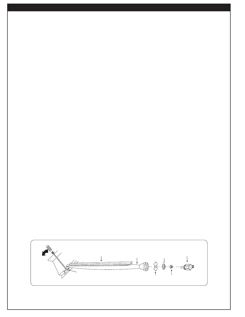
Air shutter
Burner
manifold with
orifice holder
Burner
Orifice
Spring
Burner neck
Burner clip
Fig.
12-1
- Burner orifi ce diagram