Important, 4 replacing the shredder knives – Echo Bear Cat 70580 v.1 User Manual
Page 20
3 INCH CHIPPER/SHREDDERS
18
SERVICE & MAINTENANCE
BEFORE INsPECTINg OR sERvICINg ANy PART OF THIs mACHINE, sHuT OFF POWER sOuRCE,
dIsCONNECT sPARk PLug WIRE FROm sPARk PLug ANd mAkE suRE ALL mOvINg PARTs HAvE COmE TO A COmPLETE sTOP.
Warning
5 . 3 S e T T i n g c h i P P i n g b l a d e
clearance
The chipping blades should clear the chipper block, located inside
the frame on the bottom edge of the chipper chute intake, by 1/16"
to 1/8". To adjust the blade clearance, proceed as follows:
Remove the rotor shaft end cap and upper shield.
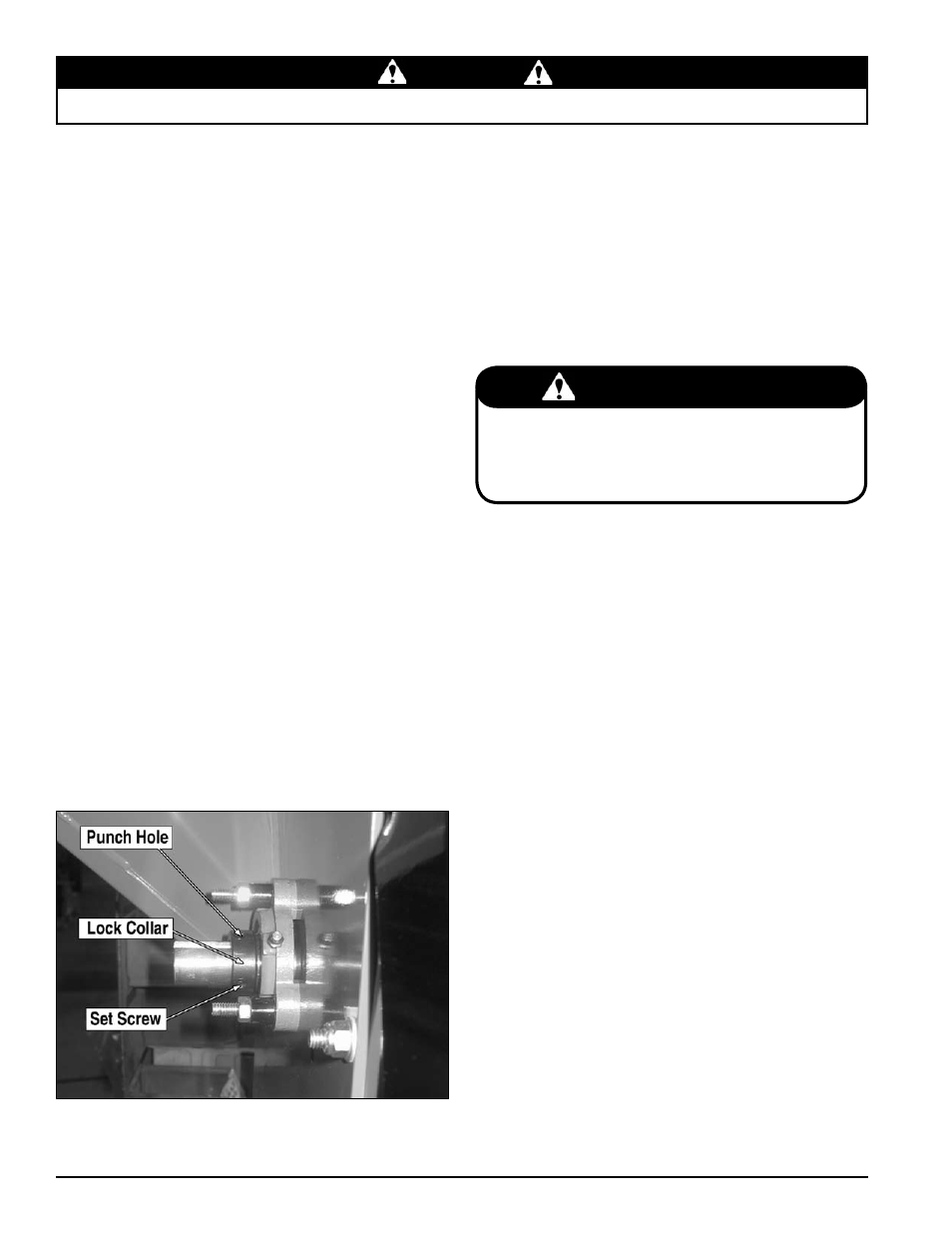
Loosen the set screws holding the lock collars on the chute
side and engine side bearings (Figure 5.3).
use a punch and hammer to tap the lock collars in the oppo-
site direction of normal rotation.
on the chute side bearing,
tap punch in a cW rotation. on the engine side bearing,
tap punch in a ccW rotation
using a rubber mallet tap the end of the rotor shaft to obtain
1/16" to 1/8" clearance. Rotate the rotor and check the clear-
ance on all chipping blades.
Once clearance has been set, the lock collars must be re-
placed and retightened. using a punch and a hammer, tap
the lock collars in the direction of shaft rotation
(clockwise
on the engine side bearing and counterclockwise on
the chute side bearing) and set them with a hammer tap.
Tighten the lock collar set screws.
Loosen the set screws holding the belt pulley on the rotor
shaft. move the pulley on the shaft so it is aligned with the
engine drive pulley. The pulley should be moved the same
amount the rotor was moved, only in the opposite direction.
Torque pulley set screw to 160 In-lbs.
Insure the pulley drive key is completely seated under the
pulley and tighten the set screws.
Check pulley alignment by laying a straightedge across the
pulley faces. Pulley faces should line up. If not, repeat steps
6 and 7 until the pulley is lined up.
1.
2.
3.
4.
5.
6.
7.
8.
Remove the lower belt guard from under engine frame,
remove discharge door and discharge screen.
Remove the 10-24 x 1-3/8" bolts and nuts from knife
shafts.
Align shaft with the 5/8" hole in rear of frame and the small
hole in front of frame by the chipper chute.
using a small punch or rod, push the shaft out the 5/8" hole
in rear of frame.
To assemble, insert shaft through the 5/8" hole in rear of
frame and slide knives and spacers in their proper order onto
the shaft.
install a new 10-24 x 1-3/8" bolt and nut.
Repeat steps 3 through 6 to assemble the other three
shafts.
When completed, install the discharge screen, discharge door
and torque all 3/8" bolts to 33 Ft-lbs. Test run machine.
1.
2.
3.
4.
5.
6.
7.
5.4 rePlacing The Shredder kniveS
The Rectangular shredder knife kit is a replacement kit to
replace existing dull or damaged knives. The serrated shredder
knives are designed to offer long life and can be reversed if they
become dull. This shredder kit uses an improved knife pattern to
provide more complete shredding, durability, and easier feeding.
Ensure the knives and spacers are properly installed to maintain
rotor balance.
Refer to the Parts manual for shredder knife kit. To remove the
knives or to install a new shredder kit proceed as follows.
imPorTanT
The serrated edge of the shredder knives should face the
same direction as the cutting edge of the chipper blades.
Never reuse the #10-24 nut and bolt. Never reuse shafts or
spacers if they show signs of wear or abuse. Always install
new parts when repairing.
Figure 5.3 - Lock Collar