Warning, Features & controls, Use of controls – Echo Bear Cat 73554 User Manual
Page 19
Page 16
Bearcat Chipper Shredder Operator’s Manual
Features & Controls
USE OF CONTROLS
TOWABLE MODELS
(Model # 73525)
1.
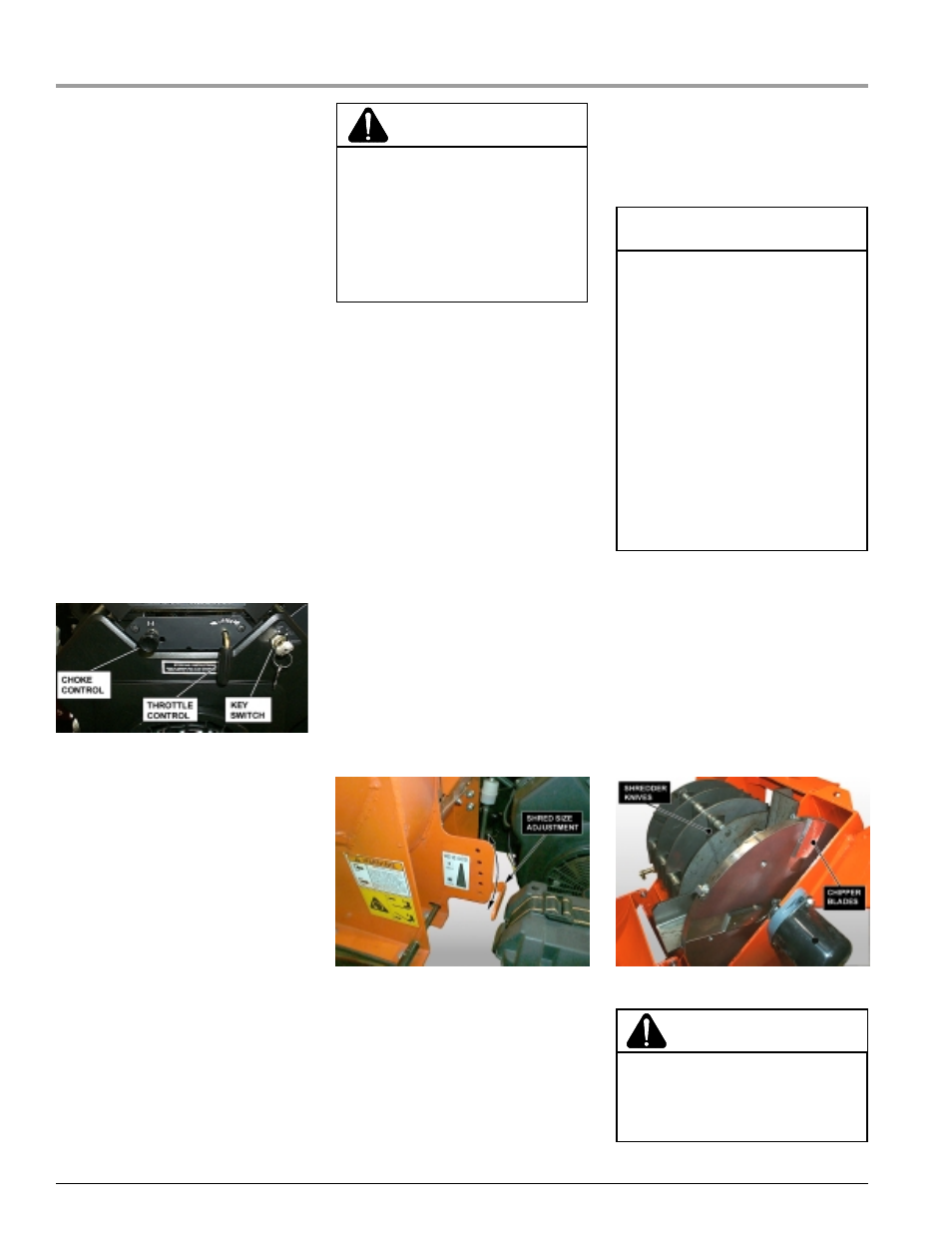
Engine Throttle: Changes engine
speed. Push lever to fast for start-
ing and operating. Push lever to
slow for idle and warm-up. Push
throttle lever to 1/2 throttle to shut
engine off. Refer to engine manual
for further engine operating instruc-
tions.
2.
Engine Choke: Use when start-
ing cold engine. Move lever to
choke position when starting.
Move lever to run position when
engine is running. Refer to engine
manual for further engine operat-
ing instructions.
3.
Key Switch: Start the engine by
activating the key switch. Release
the switch as soon as the engine
starts. Refer to engine manual for
further engine operating instruc-
tions.
4.
Clutch Lever: Engages chipper/
shredder rotor. Depress lever down
slowly with engine running to dis-
engage rotor. With a new drive belt
the rotor may rotate with the clutch
disengaged. Within a short break
in period the belt will relax and the
clutch should disengage. If the
clutch does not disengage even af-
ter a break in period, check pulley
alignment and clutch mechanism
or return to your dealer for service.
(See Section 5 for replacing the
drive belt). When disengaging the
rotor, especially at full throttle, the
rotor will rotate for some time until
it stops.
5.
Shredder Chute: Materials to be
shredded are fed through the shred-
der chute to the shredder knives.
6.
Chipper Chute: Materials to be
chipped are fed through the chip-
per chute to the chipper blades.
7.
Discharge Tube: Chips and
shredded material exit through the
top opening in the discharge tube.
The discharge chute can be rotated
to direct the material at 22.5° in-
crements. The discharge tube can
be further adjusted by rotating the
discharge deflector. Loosen the
knobs located on both sides of the
discharge deflector and adjust to
desired angle, retighten both
knobs.
8.
Shredder Adjuster: Shredded
material is retained in the shred-
der chamber by adjusting the
shredder lever up or down. Move
the shredder adjuster lever up to
provide smaller sized shredded
material. Move the shredder ad-
juster lever down to provide larger
sized shredded material.
9.
Jack Stand: Always have the jack
stand retracted from the ground
when moving the unit. When in
use, be sure the jack stand is
down and locked in position with
the snap pin.
WARNING
To prevent personal injury or prop-
erty damage: Shut off engine, dis-
connect spark plug wire, remove
ignition key and make sure that all
moving parts have come to a com-
plete stop, before servicing, adjust-
ing or repairing.
10. Safety Switch: This machine is
equipped with a engine kill safety
switch which prevents the the en-
gine from starting unless the knive
access cover is closed.
11. Knive Access Cover: The knive
access cover is used to access
the shredder knives and chipper
blades.
12. Chipper Blades: The chipper
blades chip material that is fed into
the chipper chute.
13. Shredder Knives: The shredder
knives shred material that is fed
into the shredder chute.
Fig. # 5 Shredder adjuster
Fig. # 4 Engine controls
WARNING
To avoid personal injury or property
damage:
• Never attempt to disconnect or
to otherwise defeat the purpose of
this system.
• If the engine kill safety switch fails
to operate correctly, shut off the
machine and do not operate this
equipment until the system has
been repaired and is functioning
properly.
• Be sure to fasten the knive ac-
cess cover with the knive access
cover bolt before attempting to op-
erate the machine.
WARNING
Guards and shields are removed for
illustrative purposes only; do not op-
erate without guards and shields in
place and functioning properly.
Fig. # 6 Chipper blades & shredder knives