Installation and mounting / front panel controls – Drake SCT2x4 BBT Transcoder User Manual
Page 6
6
INSTALLATION AND MOUNTING NOTES
this equipment is designed to be installed in a standard 19” rack. when the unit is mounted above or below other
rack mounted equipment, a 1U space (1.75”) should be left between the unit and the other equipment to allow
ambient air flow between the units. No space is needed between adjacent SCt2x4 units themselves due to the
ventilation provided by their built in fans.
Connect the AC line cord to an appropriate source of 120 volt, 50/60 Hz AC power. the SCt2x4 is always on
once the AC power cord is connected to its power source.
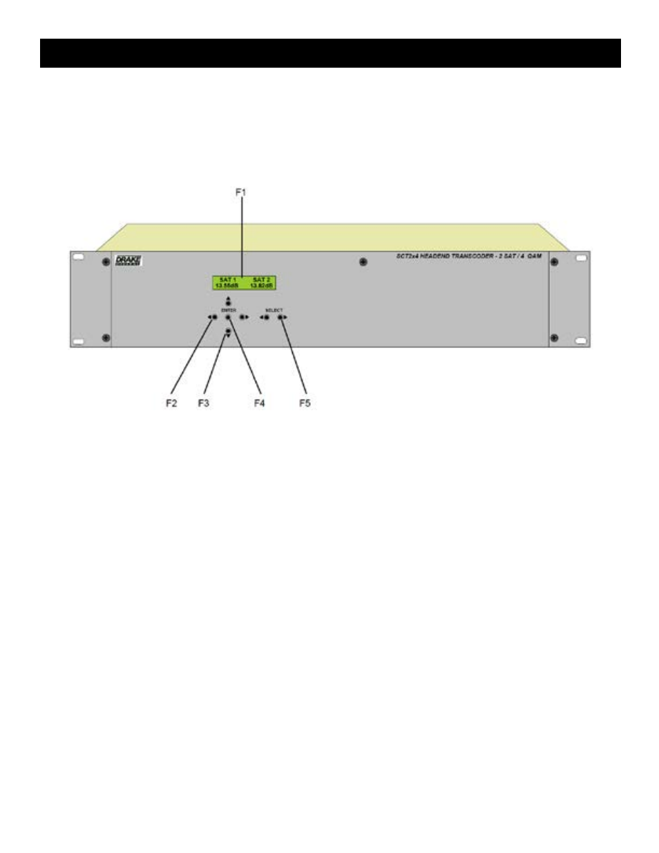
F1, LCD Display - this display presents the selected menu screen and the parameter settings. the backlight in
the display is on when power is applied.
F2, Left and Right Buttons – Use the left and right arrow buttons to navigate from screen to screen to view a
parameter setting within a particular program group. these buttons are operational in the view mode or the adjust
mode. Using only these buttons will not change any parameter setting.
F3, Up and Down Buttons – Use the up and down arrow buttons to change the value of a viewed parameter
setting. the unit must be in the adjust mode in order for these buttons to become active for changing a parameter
setting. if the unit is not in the adjust mode and program group ‘iNPUtS’ has been selected using the ‘SeLeCt
Left and Right Buttons (f5), pressing the UP button will toggle between the ‘SAt 1 SAt 2’ screen and the ‘fw
version’ screen. Pressing the DowN button will toggle between the ‘SAt 1 SAt 2’ screen and the ‘StAt2 StAt3’
screens. If QAM 1 through QAM 4 have been selected, pressing the UP button will display the firmware version
number, but pressing DowN button will display the Buffer screen showing the percentage of current buffer usage
on the left and maximum buffer usage on the right for that particular qAm output.
F4, ENTER Button - Use the eNteR button to enter the adjust mode or to save and load a new setting or
settings after adjustment. Hold for approximately 2 seconds until the bottom line of the display starts to flash to
enter the adjust mode. After entering the adjust mode, momentarily pressing the eNteR button again will load
and save any settings that may have been changed using the Up and Down buttons.
F5, Left and Right SETUP SELECT Buttons - Use the left and right SetUP SeLeCt buttons to navigate
through the 7 available programming groups. the selection of the desired parameters within each of these groups
can then be made using the Left and RiGHt (f2), UP and DowN (f3), and eNteR (f4) buttons these groups
are as follows:
INPUTS - Allows observation and selection of several parameters for the SAt 1 and SAt 2 inputs.
QAM 1, QAM 2, QAM 3, & QAM 4 - Allows observation and selection of parameters for each of the four qAm
outputs.
Installation and Mounting / Front Panel Controls