Road towable kit, Installing the road towable kit – DR Power Towable Backhoe User Manual
Page 25
CONTACT US AT www.DRpower.com 25
Road Towable Kit
Tools and Supplies Needed:
•
7/16" Wrench
•
1/2" Wrench
•
9/16" Wrench
•
Wire Cutters
Installing the Road Towable Kit
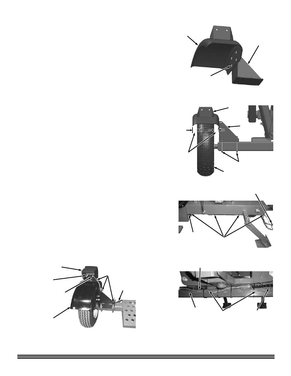
1.
Assemble the Mounting Bracket and Roadside Fender with four 5/16-18 x
3/4" Carriage Bolts and Locknuts using a 1/2" Wrench (Figure 41).
2.
Position the Fender and Mounting Bracket onto the roadside of the Backhoe
Axle so the Fender protrudes evenly over both sides of the Tire (Figure 42)
and secure the Mounting Bracket with the two U-bolts and 3/8-16 Locknuts
using a 9/16" Wrench. Repeat steps 1 and 2 for the Curbside Fender and
Mounting Bracket.
NOTE: Push the Mounting Brackets towards the Tow Hitch side of the Axle as you
tighten the U-Bolt Locknuts.
3.
Place the Vehicle Connector end of the Wire Harness near the Tow Hitch.
Push the Tail Light Connectors and Ground Wires through the hole in the
Frame (Figure 43).
4.
Guide the Wires between the Frame and Axle and then route the
Yellow/Brown Wire Connector with a White Ground Wire along the Axle
towards the roadside of the Backhoe and the Green/Brown Wire Connector
with a White Ground Wire along the Axle towards the curbside (Figure 44).
5.
Position the Curbside Tail Light (green/brown wires) and Roadside Tail
Light (yellow/brown wires) onto the Fenders and secure each with one of
the Locknuts on the outside stud using a 7/16" Wrench (Figure 45).
6.
Place a Ground Wire from the Harness onto the other stud and secure with
the second Locknut.
7.
Plug in the two Harness Connectors to the Lights and secure the Wires with
three Cable Ties on each side.
8.
Let the Vehicle Connector extend about two feet past the Hitch and attach
the Harness to the Backhoe with four Cable Ties at the locations shown
(Figure 43).
9.
Fasten the wires to the Axle with Cable Ties along with any excess wire from
the Harness (Figure 44). Trim all Cable Ties with Wire Cutters.
Roadside
Fender
Figure 41
Mounting
Bracket
Carriage Bolts
(Fender side)
and Locknuts
Mounting
Bracket
Figure 42
U-Bolts and
Locknuts
Equal
distance
Roadside
Fender
Tire
Figure 43
Cable Tie
Locations
Hole in
Frame
Vehicle Connector
This End
Cable
Ties
Figure 45
Curbside
Fender
Curbside
Tail Light
Nylon
Locknuts
Green and
Brown Wire
Connector
Ground
Wire
Yellow and
Brown Wires
(roadside)
Figure 44
Green and
Brown Wires
(curbside)
White
Ground Wire
(both sides)
Axle