Adjusting the shredder hammers – DR Power 8 FPT User Manual
Page 22
22
DR
®
CHIPPER/SHREDDER
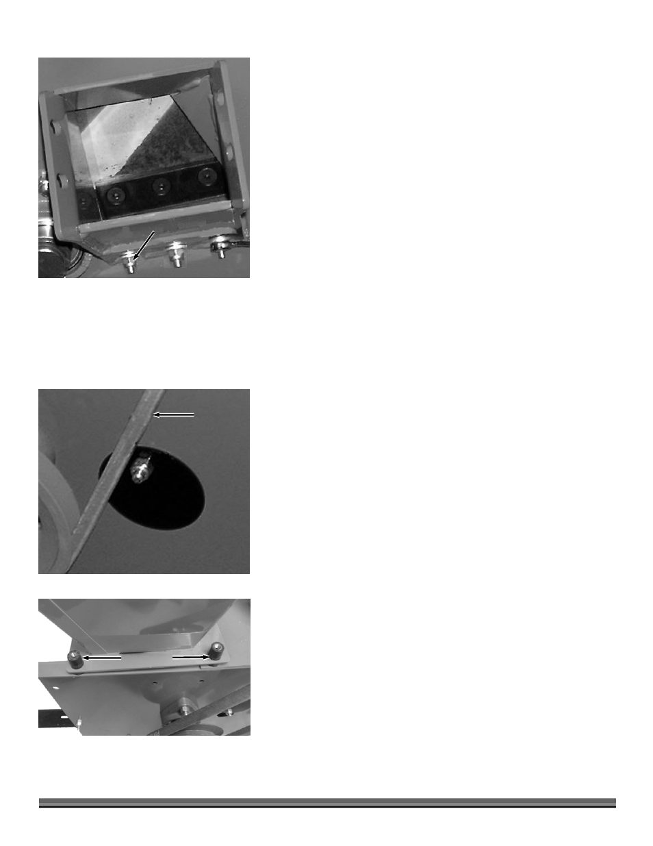
4. To adjust the Wear Plate Gap, loosen the three 1/4" Nuts using a 7/16"
Wrench (Figure 25). Now slide the Wear Plate up or down (in or out) to
achieve the correct gap setting.
5. Tighten the Nuts when the Wear Plate is in the correct position (Figure 23 on
page 21).
6. Replace the Chipper Hopper.
NOTE: After any Knife or Wear Plate maintenance or adjustment, rotate the
Chipper Disk watch and listen carefully for any unusual noises, clicking or vibration.
If you detect any of these, inspect the machine for damage, or any loose parts.
Repair or replace any damaged parts and tighten any loose parts before starting the
DR Chipper/Shredder.
Adjusting the Shredder Hammers
When the hard steel Hammers of the Rotor Assembly become dull or round on the cutting edge, they may be rotated or reversed.
NOTE: The Hammers have four cutting edges that may be used before replacement is necessary. To reverse the Hammers, proceed as
follows:
Tools and Part Required
(2) 1/2" Wrench
Hammer and Punch
(4) Grooved Pin, P/N 186180
Vise Grips
1. Remove the Belt Guard (page 18) and the Baffle Plate (page 16).
2. Loosen the 5/16" Nut and rotate the round Access Cover Plate to expose the
Access Hole (Figure 26).
3. Using two 1/2" Wrenches, remove the Shredder Hopper (Figure 27) by
removing the four (4) Bolts (hold the Nuts on top while backing out the
Bolts) from the Vibration Dampers. Note that the Rear Bolts are 1-1/2" and
the Front Bolts are 1-1/4" long. Lift the Hopper off with the Vibration
Dampers in place (Figure 27).
4. Rotate the Hammer(s) Rod until the Deep Grooved end of the Groove Pin at
the end of the Rod is pointing down (Figure 28 on page 23).
5. While holding the Hammer(s) Rod in place with Vise Grips, drive out the
Groove Pin with a punch (Figure 28 on page 23).
6. Rotate the Hammer assembly until the Rod is lined up with the Access Hole.
7. Carefully remove the Rod through the Access Hole and at the same time
remove the Hammers and spacers from the Rod leaving them in the same
order as you removed them.
8. Now reverse each Hammer (end to end) by using the lower hole in the
Hammer.
Figure 25
Wear Plate Nuts
3 places
Figure 26
Access Cover
Belt
Vibration Dampers
2 each side
Shredder Hopper
Figure 27