Diamondback 500ER User Manual
Page 12
12
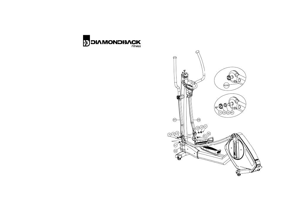
18. The forward pivots of the step arms (K2 & K3)
will arrive with the fixing hardware
pre‐installed as depicted in Fig. 4.A. Remove
the hardware assembly (parts J1, J2 and J3)
from the step arms and set aside.
19. Spacer K1 should remain in place on the pivot
axles.
20. Bring the pivots of the left step arm (K3) and
handlebar together. Slide the handlebar pivot
over the step arm pivot axle and press into
place.
21. Thread fixing nut J3 onto the pivot axle and
tighten with the provided wrench.
22. Insert hex screw J1 through pivot cap J2 and
tighten with the included hex key.
23. Repeat this process for the right side
assembly.
Fig. 4.A.
Fig 4.B.