DFI NP102-N16C User Manual
Page 28
28
2
Hardware Installation
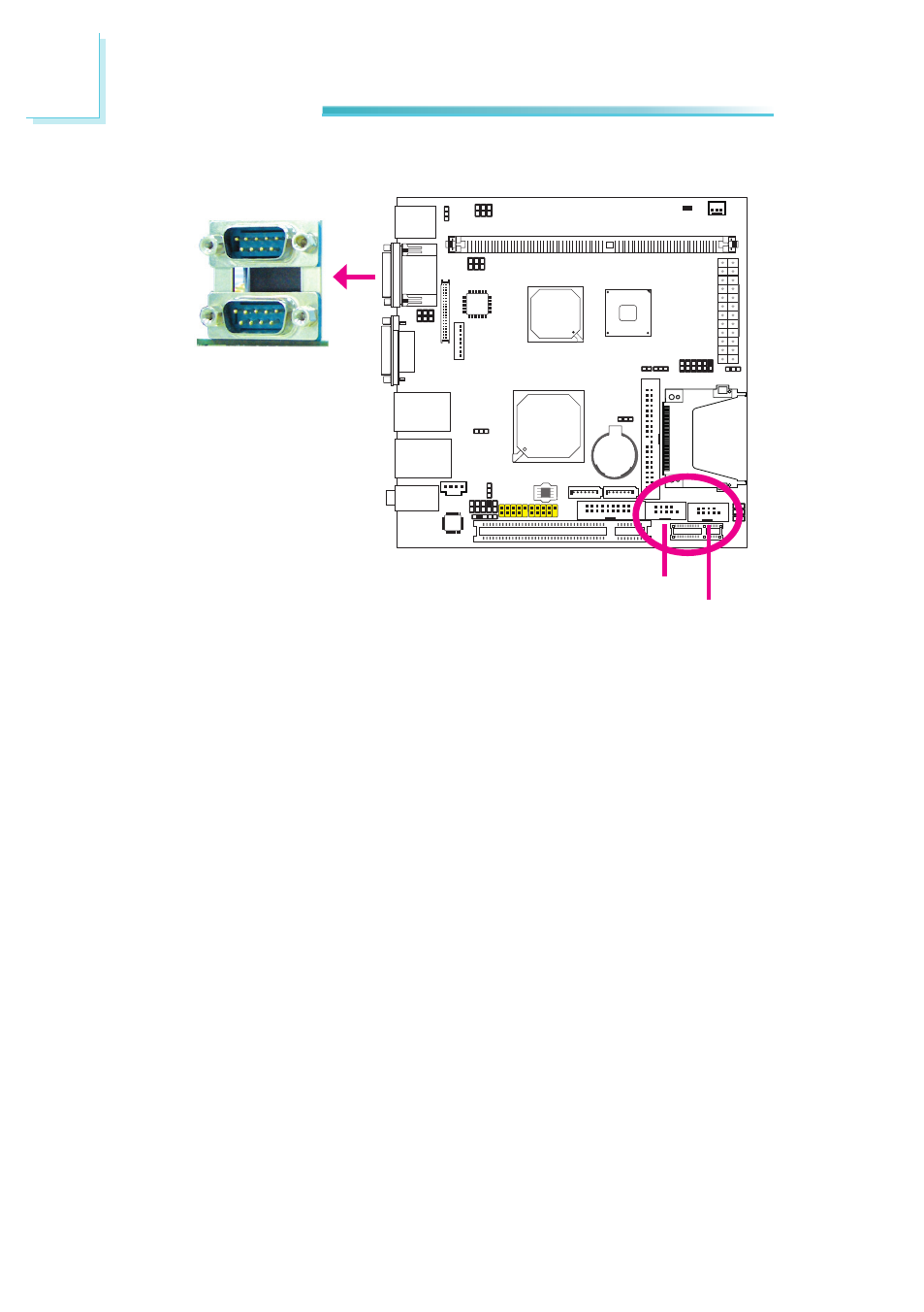
COM (Serial) Ports
COM 1
COM 2
COM 4
COM 3
COM 1 and COM 2’s pin definition will vary according to JP11 and JP9’s settings.
Refer to “COM1/COM2 RS232/RS422/RS485 Select” in this chapter for more in-
formation.
COM 3 and COM 4 are fixed at RS232. You may set COM 3 to support auxiliary
power by configuring JP10. Refer to “COM 3 RS232/Power Select” in this chapter
for more information.
The serial ports are asynchronous communication ports with 16C550A-compatible
UARTs that can be used with modems, serial printers, remote display terminals,
and other serial devices.
Connecting External Serial Ports
Your COM port may come mounted on a card-edge bracket. Install the card-edge
bracket to an available slot at the rear of the system chassis then insert the se-
rial port cable to a COM connector. Make sure the colored stripe on the ribbon
cable is aligned with pin 1 of the COM connector.
BIOS Setting
Configure the serial ports in the Integrated Peripherals submenu (“Super IO De-
vice” section) of the BIOS. Refer to chapter 3 for more information.