Chapter 2 – DFI SB102-D User Manual
Page 27
www.dfi.com
27
Chapter 2 Hardware Installation
Chapter 2
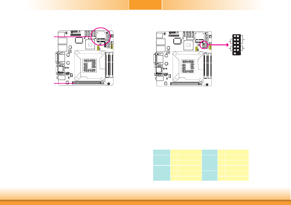
Front Panel Connector
HDD-LED - HDD LED
This LED will light when the hard drive is being accessed.
RESET SW - Reset Switch
This switch allows you to reboot without having to power off the system.
PWR-BTN - Power Switch
This switch is used to power on or off the system.
PWR-LED - Power/Standby LED
When the system’s power is on, this LED will light. When the system is in the S1 (POS - Power
On Suspend) state, it will blink every second. When the system is in the S3 (STR - Suspend To
RAM) state, it will blink every 4 seconds.
HDD-LED
RESET-SW
PWR-LED
PWR-BTN
12
11
2
1
Pin Pin Assignment
Pin Pin Assignment
HDD-LED
3
HDD Power
PWR-LED
2
LED Power
5
Signal
4
LED Power
RESET SW
7
Ground
6
Signal
9
RST Signal
PWR-BTN
8
Ground
11 N.C.
10
Signal
Expansion Slots
PCI Express x16 Slot
Install PCI Express x16 graphics card, that comply to the PCI Express specifications, into the
PCI Express x16 slot. To install a graphics card into the x16 slot, align the graphics card above
the slot then press it down firmly until it is completely seated in the slot. The retaining clip of
the slot will automatically hold the graphics card in place.
Mini PCIe Slot
The Mini PCIe socket is used to install a half size Mini PCIe card. Mini PCIe card is a small
form factor PCI card with the same signal protocol, electrical definitions, and configuration
definitions as the conventional PCI. It supports PCIe and USB signals. The Mini PCIe slot does
not support mSATA.
PCI Express x16
Mini PCI Express