Chapter 2, Power connectors, Standby power led – DFI SB102-D User Manual
Page 26
www.dfi.com
26
Chapter 2 Hardware Installation
Chapter 2
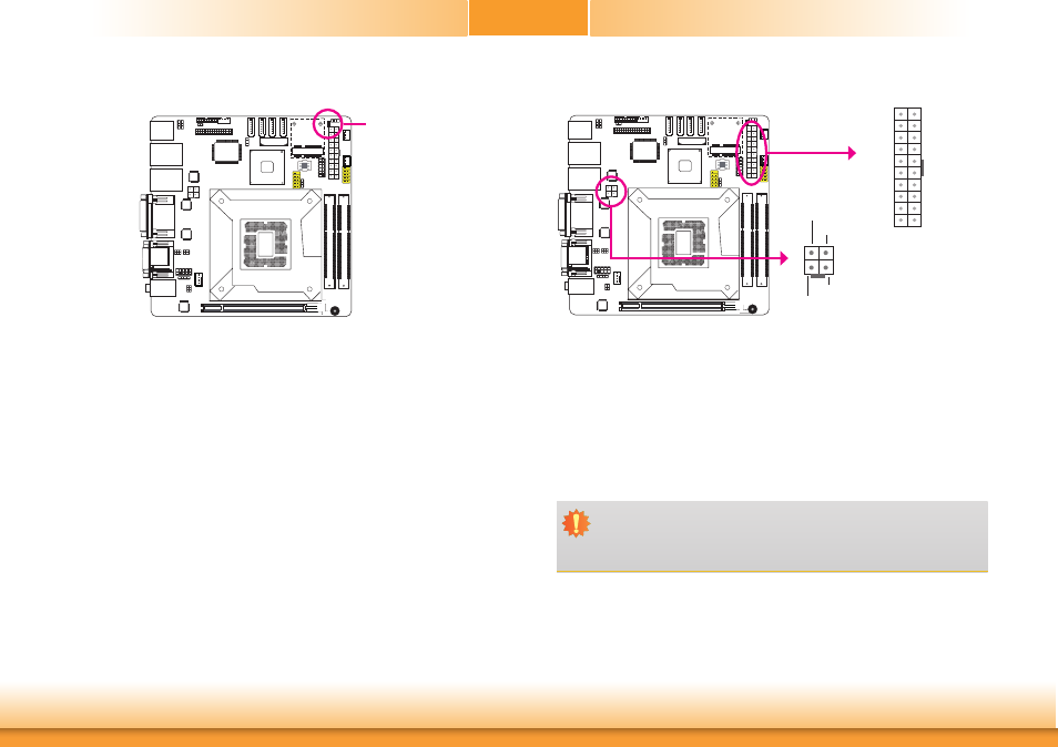
Power Connectors
Use a power supply that complies with the ATX12V Power Supply Design Guide Version 1.1.
An ATX12V power supply unit has a standard 20-pin ATX main power connector that must be
inserted into the 20-pin connector. The 4-pin +12V power connector enables the delivery of
more +12VDC current to the processor’s Voltage Regulator Module (VRM).
The power connectors from the power supply unit are designed to fit the 20-pin and 4-pin
connectors in only one orientation. Make sure to find the proper orientation before plugging
the connectors.
The system board requires a minimum of 300 Watt power supply to operate. Your system
configuration (CPU power, amount of memory, add-in cards, peripherals, etc.) may exceed the
minimum power requirement. To ensure that adequate power is provided, we strongly recom-
mend that you use a minimum of 400 Watt (or greater) power supply.
Important:
Insufficient power supplied to the system may result in instability or the add-in boards
and peripherals not functioning properly. Calculating the system’s approximate power
usage is important to ensure that the power supply meets the system’s consumption
requirements.
1
3
2
4
Ground
Ground
+12V
+12V
ATX power
11
10 20
1
3.3V
3.3V
GND
+5V
GND
+5V
GND
PW-OK
5VSB
+12V
3.3V
-12V
GND
PS-ON
GND
GND
GND
-5V
+5V
+5V
ATX 12V
Standby Power LED
Standby Power LED
This LED will lit red when the system is in the standby mode. It indicates that there is power
on the system board. Power-off the PC and then unplug the power cord prior to installing any
devices. Failure to do so will cause severe damage to the motherboard and components.