Chapter 2 – DFI Q7X-151 User Manual
Page 21
www.dfi .com
Chapter 2 Hardware Installation
21
Chapter 2
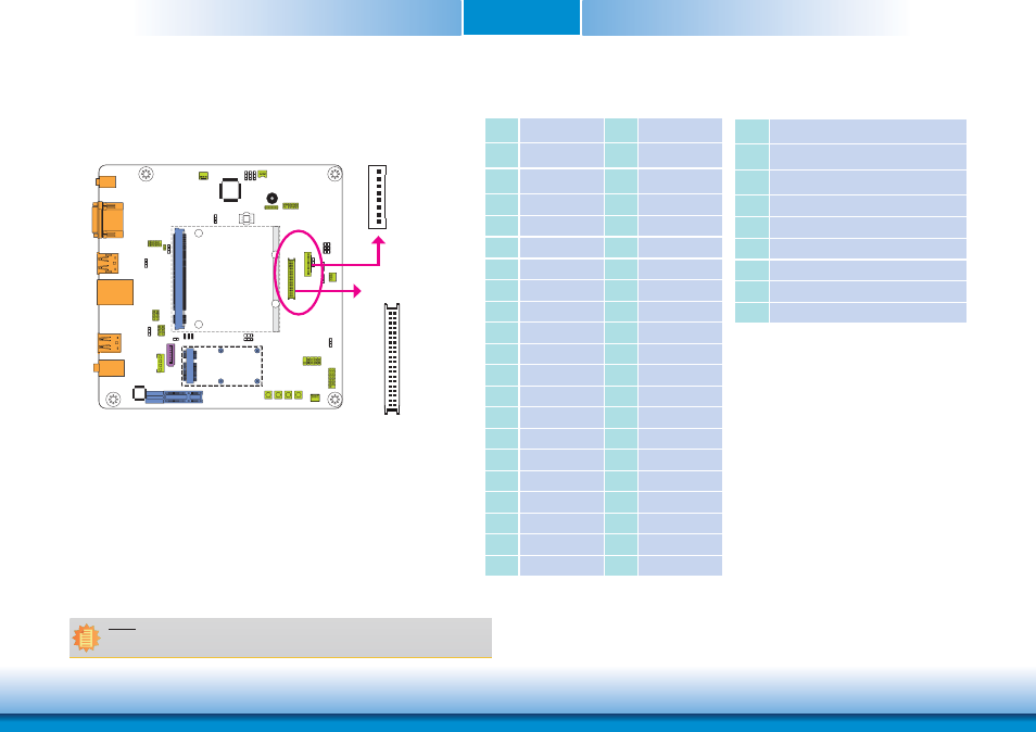
LVDS LCD Panel Connector
LCD/Inverter Power Connector
The system board allows you to connect a LCD Display Panel by means of the LVDS LCD
panel connector and the LCD/Inverter power connector. These connectors transmit video
signals and power from the system board to the LCD Display Panel.
Refer to the right side for the pin functions of these connectors.
Jumper Settings
Refer to the “Jumper Settings” section in this chapter for settings relevant to the LCD
panel.
LVDS LCD Panel Connector
LCD/Inverter Power Connector
Pins
Function
Pins
Function
1
GND
2
GND
3
LVDS_Out3+
4
LVDS_Out7+
5
LVDS_Out3-
6
LVDS_Out7-
7
GND
8
GND
9
LVDS_Out2+
10
LVDS_Out6+
11
LVDS_Out2-
12
LVDS_Out6-
13
GND
14
GND
15
LVDS_Out1+
16
LVDS_Out5+
17
LVDS_Out1-
18
LVDS_Out5-
19
GND
20
GND
21
LVDS_Out0+
22
LVDS_Out4+
23
LVDS_Out0-
24
LVDS_Out4-
25
GND
26
GND
27
LVDS_CLK1+
28
LVDS_CLK2+
29
LVDS_CLK1-
30
LVDS_CLK2-
31
GND
32
GND
33
LVDS_DDCCLK
34
N.C.
35
LVDS_DDCDAA
36
+3.3V
37
Panel Power
38
Panel Power
39
Panel Power
40
Panel Power
Pins
Function
1
GND
2
GND
3
Panel Inverter Brightness Voltage Control
4
Panel Power
5
+3.3V
6
Panel Backlight On/Off Control
7
LCD/Inverter Power
8
LCD/Inverter Power
Note:
DFI board's LVDS connector: Hirose DF13-40DP-1.25V(91)/40P/1.25mm; cable side
connector: Hirose DF13-40DS-1.25C.
LCD/Inverter
power
1
8
LVDS LCD Panel
2
1
40
39