Chapter 3 – DFI CR901-B User Manual
Page 29
www.dfi .com
Chapter 3 Hardware Installation
29
Chapter 3
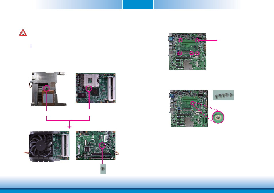
Installing CR901-B onto a Carrier Board
Important:
The carrier board (COM331-B) used in this section is for reference purpose only and
may not resemble your carrier board. These illustrations are mainly to guide you on
how to install CR901-B onto the carrier board of your choice.
Mounting screw
1. Use the provided screw to install the heatsink onto the module. First align the mounting
hole of the heatsink with the mounting hole of the module and then from the bottom
side of the module, secure them with the provided screw. The module and heatsink as
sembly should look like the one shown below.
Mounting hole
Mounting hol
e
bottom side of heat sink
Top view
Bottom view
Mounting hole
2. Now install the module and heatsink assembly onto the carrier board. The photo below
shows the locations of the mounting holes on carrier board.
3. Insert the provided mounting screws into the mounting holes - from the bottom through
the top of the carrier board.
Mounting screws
•