Chapter 3 - hardware installation, Board layout, Block diagram – DFI CR900-B User Manual
Page 10: A/ b c / d, Processor, Mobile intel, Qm77 express chipset
www.dfi.com
Chapter 3 Hardware Installation
10
Chapter 3
Chapter 3 - Hardware Installation
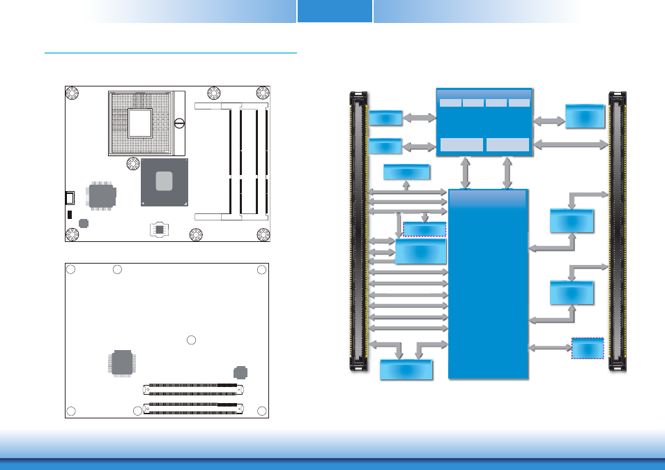
Board Layout
Top View
Bottom View
Standby Power LED
S
ocket
G2
rPGA
-988B
Intel 82579LM
D
D
R3_2
SOD
IMM
D
D
R3_1
SOD
IMM
1
CPU fan
Intel
QM77
iTE
IT8892E
SPI Flash
BIOS
COM Express connector
B1
C1
D1
B110
C110
D110
A1
A110
COM Express connector
iTE
IT8518E
JMB
368
Block Diagram
IDE Bus
SSD Chip
(
option
)
IMVP7
(Vcore,Vgfx)
PEG 16x LANES
Channel A
1066/1333/
1600MHz
CMOS Backup
EEPROM
LPC TPM 1.2
SLB9635(option)
GPIO,WDT,I
2
C
(Embedded
Controller)
PCIe x1, Lane 1-5
CRT
USB 2.0 8x
LVDS (Dual Channel)
2
nd
SPI Bus
2
nd
Generation;
Intel
®
Core
™
i7/i5/i3; Intel
®
Celeron
™
CORE
Processor
CORE CORE CORE
Graphics
CORE
Memory
Controller
DMI x4
(Direct Media
Interface)
Intel
®
FDI
(Flexible Display
Interface)
DDR3
SODIMM
1600MHz
Mobile Intel
®
QM77
Express Chipset
SM Bus
HD Audio
LPC Bus
Intel
®
GLAN
PHY 82579LM
LAN Ports
A
/
B
C
/
D
DDR3
SODIMM
PEG 16x LANES
SM Bus
SM Bus
HD A di
SM Bus
HD Audio
LPC Bus
LPC Bus
USB 2.0 8x
CRT
LVDS (Dual Channel)
PCI
1 L
1 5
CRT
PCIe x1, Lane 1 5
nd
2 SPI Bus
LAN Ports
3
rd
Generation;
Intel
®
Core
™
i7/i5/i3
PCIe x1, Lane 8
IT8892E
PCIe to
PCI Bridge
PCIe x1,Lane 7
PCI Bus
PCI Bus
PCIe x1,Lane 7
PCIe x1, Lane 6
IDE Bus
PCIe x1, Lane 6
PCIe to
PATA
JMB368
SATA 2.0 2x, SATA 3.0 2x
SATA Port4
Channel B
1066/1333/
1600MHz
8-bit DIO
WDT
I
2
C Bus
I
2
C Bus
WDT
C us